
Page 156 - Zero Net Energy Case Study Buildings-Volume 3
P. 156
CASE STUDY NO. 17 CENTRAL ENERGY FACILITY OPERATIONS CENTER
(Opposite page, top) Diagram of ZNE design features for the CEF Operations Center. (Courtesy of ZGF Architects.)
(Opposite page, bottom) Inte- rior view, CEF Control Room for monitoring and optimizing campus systems performance.
(Following pages, overleaf)
View of interior courtyard and amphitheater designed as part of exterior stairs to the second floor level.
142
Daylighting and Electric Lighting
The office space is well-daylighted with tall glass on both sides of the narrow (30’) floor plate. The shading from the extensive solar canopy prevents direct glare conditions. The optimal spac- ing of the opaque canopy elements for this purpose was studied during the design phase using shading mask analysis.
Natural Ventilation
User-controlled operable windows allow for natural ventilation when outside conditions warrant in this year-round temperate climate. Since the designers and client opted for user-control, night flushing to precool the building during peak cooling weather events is not possible.
Heating, Ventilating and Cooling Systems
The office building utilizes a radiant floor system throughout for heating and cooling, with addi- tional climate control provided by ancillary systems. Radiant systems generally require less en- ergy and provide greater comfort than all-air systems and are an ideal system for office spaces.
The radiant system in this case is a “single-pipe” system, which requires a “dead band” in the op- eration between the heating and cooling modes. This generally occurs, for example, when foggy mornings give way to warm and sunny afternoons, an occasional event in this microclimate.
The ancillary systems were added in part at the behest of the users, who wanted to use the building as a test facility for new systems and technologies that might be considered for future buildings on the Stanford campus.
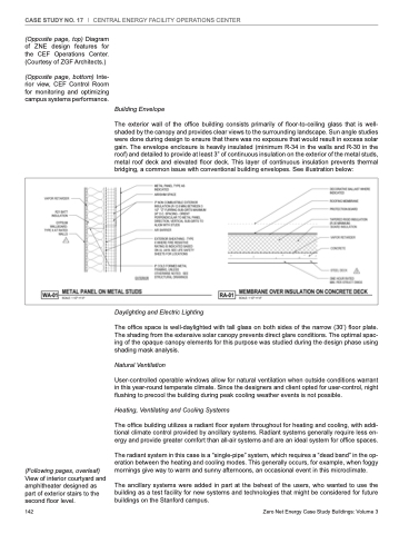
Building Envelope
The exterior wall of the office building consists primarily of floor-to-ceiling glass that is well- shaded by the canopy and provides clear views to the surrounding landscape. Sun angle studies were done during design to ensure that there was no exposure that would result in excess solar gain. The envelope enclosure is heavily insulated (minimum R-34 in the walls and R-30 in the roof) and detailed to provide at least 3” of continuous insulation on the exterior of the metal studs, metal roof deck and elevated floor deck. This layer of continuous insulation prevents thermal bridging, a common issue with conventional building envelopes. See illustration below:
Zero Net Energy Case Study Buildings: Volume 3
