
Page 161 - Zero Net Energy Case Study Buildings-Volume 3
P. 161
A second ancillary “system”, used throughout the building, is a blanket-type phase change mate- rial (PCM) as a passive cooling technique, acting like thermal mass to absorb heat at a constant temperature rather than causing an increase in room air temperature. These PCMs are located above and on the suspended ceiling, where they can interact with the room environment.
These materials absorb heat from the space above a certain temperature (called the “Q-value”) and gradually become liquified. To perform the same function on the following day, the material must be exposed to a lower temperature and returned to a solid state during the night. This is accomplished by using a small exhaust fan at night in the plenum space only, where the PCM is located, to chill down that space so that the PCM is fully re-charged for the next day. Measure- ments are currently being done of the effectiveness of this system to reduce the peak of the cooling load.
Renewable On-Site Energy Supply
As described above, the large cross-laminated wood canopy structure placed above the office building supports the solar PV panels. It also provides an architectonic element intended to be reminiscent of the trellises over other campus courtyards while providing shading of the glass facades on the second floor. It was not sized to support a specific number of solar PV panels that would offset the building’s annual energy consumption.
Originally, the cross-laminated panels were installed for shading purposes. It was not until March, 2017, that the solar PV system totaling 175 kW was installed on the canopy and started to pro- duce power that could be utilized by the building. Because PV panels were installed everywhere on the canopy, the system actually has a large over-production, which is put into the general campus power grid.
Energy Design Analysis and Energy Performance
Modeling versus Post-Occupancy Measurement
Energy Modeling
Energy modeling was initially done using eQuest (2010) for the basic building and systems that were capable of being modeled at that time. Additional techniques of calculating the effective- ness of non-standard systems, including the use of custom spreadsheets, were utilized and added to the eQuest results to gauge the overall performance expected for the building. The high process energy requirements of the campus CEF control room and server room were only partly known the time, so a meaningful overall energy model for the building was not obtained.
Monthly results of the breakdown by category of energy use were not derived, but there was confidence by the design team and Stanford representatives based on the overall analysis that the design was highly energy efficient and met all required sustainability objectives.
CENTRAL ENERGY FACILITY OPERATIONS CENTER CASE STUDY NO. 17
One of these ancillary systems was ceiling-mounted chilled sails, which was added in the con- ference spaces on the first floor to respond to the sudden increase in cooling load caused by a large increase in the number of occupants. Since the radiant floor system is located in a concrete slab, the response time would have been too long to provide comfort conditions quickly enough. Installed directly below the ceiling, the folded metal chilled sails effectively provide instant re- sponse by utilizing very effective convective heat transfer with the room air. Like chilled beams, chilled sails use chilled water and passive air movement to provide the desired thermal comfort conditions in the space. On peak cooling days, the chilled sail system is backed up by a fan-coil unit, which is used only under those more extreme conditions.
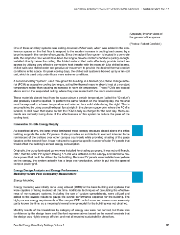
(Opposite) Interior views of the general office spaces.
(Photos: Robert Canfield.)
Zero Net Energy Case Study Buildings, Volume 3 147
