
Page 32 - Zero Net Energy Case Study Buildings-Volume 3
P. 32
CASE STUDY NO. 12 THE J. CRAIG VENTER INSTITUTE VENTILATION
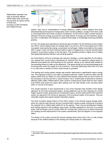
(Right) Basic operation and view of induction diffuser: chilled water (blue arrow) pip- ing and fresh air (green arrow) in small duct.
(Courtesy of ZGF Architects and Integral Group)
AIR 4-6 ACH
HEATING COOLING
INDUCTION BEAM
18
Zero Net Energy Case Study Buildings: Volume 3
LABORATORY EQUIPMENT
FUME HOOD
spaces. Now, due to considerations of energy efficiency, reliable control systems have been developed that permit lower air change rates under normal conditions, usually 4 ACH when a lab is unoccupied and 6 ACH when occupied, increasing to 12 ACH when a spill or similar toxicity is detected. Since fan energy accounts for such large fraction of energy use and therefore operat- ing cost in a laboratory, this advance in systems technology is increasingly becoming standard practice.
At JCVI, the design team specified an advanced type of system21for this demand control ventila- tion (DCV), which allowed these air change rates to be set at 2 ACH (unoccupied) and 4 ACH (occupied), reducing the fan energy consumption by half again. Safety is provided by the system with a “purge” mode (12 ACH) if sensors detect a spill or if triggered by a manual override switch located in a prominent location in the lab space. This actually provides a higher level of safety than typical laboratories that don’t use sensing systems.
As a final feature of this air exchange rate reduction strategy, a control algorithm for the labora- tory exhaust fans would reduce mechanical air exhaust from the maximum setting based on detected wind speed and wind direction at the moment, relying on the natural draft created by the prevailing breeze to make up the difference. This saves energy by not requiring bypass air at the exhaust fan when the supply air is at a minimum. This works particularly well at the JCVI site in La Jolla where a steady on-shore ocean breeze is prevalent.
The heating and cooling system design was another opportunity to significantly reduce energy use. The engineers chose to use water to transport heat and “coolth” to both the office and lab spaces rather than air. Water is a more efficient heat transfer medium than air and it would not be necessary to duct the air from a central location. Hot or chilled water is delivered to induction diffusers (often called “chilled beams” when used for cooling alone) where fresh air from nearby local DOAS units enters the space after passing over the heat transfer coils, providing either warm or cool air to the space.
The overall reduction in duct requirements is one of the important side benefits of this design approach for the total mechanical system, saving additional cost by also reducing the vertical height required overall, particularly for the laboratory space. Another side benefit of the induction system as opposed to the forced air approach is the acoustical quality of the spaces. They are noticeably quieter than typical research laboratory spaces.
The final innovative design feature of the HVAC system is the thermal energy storage tanks, which are used as heat recovery and are combined with a water-to-water heat pump to produce the required hot or chilled water called for by the spaces. There may be simultaneous heating and cooling required in the building’s many zones. Ancillary equipment in the form of a cooling tower, heat exchanger and air-cooled chiller (for cooling) and a back-up air-to-water heat pump (for heating) provide adjustments to the system operationally. (See the diagram on the opposite page.)
The design of the system around the thermal storage tanks works well in the La Jolla climate because of the relative balance of the heating and cooling loads on a daily basis.
2 Aircuity®, http://www.aircuity.com/technology/optinet-applications/lab-demand-control-ventila- tion/
