
Page 94 - Zero Net Energy Case Study Buildings-Volume 2
P. 94
CASE STUDY NO. 10
WEST BERKELEY BRANCH LIBRARY
The scheme selected for design development was therefore the one-story scheme with a pre- scribed target of maximum EUI = 20 (kBtu/sq.ft. per year) and an expected on-site energy gener- ation of 55,000 kWh from a 40 kW solar PV system1. The design would also be required to have western-style “false front” to satisfy the “two-story” frontage requirement of the city ordinance. The latter requirement also created the opportunity for a relatively high one-story public space within the building, which proved to be beneficial to the daylighting design for that space.
In general design terms, the design team chose a highly passive approach to reaching the EUI = 20 design target. In addition to focusing on daylighting as the principal opportunity for low-energy performance in this type of high-use lighting environment, the design team developed a passive method for moving air for ventilation, cooling and “night purging”. (See discussion below.)
Energy modeling throughout the design phases verified that the target EUI was being achieved through each design iteration, indicating that the building was on track to perform at a ZNE level. As noted, the ZNE design features were also checked against cost impacts to confirm that the target budget was also being achieved.
Building Envelope
The height of the main public space and the desire to minimize thermal bridging through the structural studs of the exterior wall led to a choice of 3 X 8 wood minilam2 studs for the wall fram- ing, spaced at 24” apart. Cost criteria eliminated the idea of using a layer of rigid insulation on the exterior of the framing to eliminate any thermal bridging. Rock wool insulation fills the interstitial space between the studs, providing an advantage in both total assembly R-value (R=27.2) and control of any potential issues with indoor air quality because of its inorganic properties.
A simple truss-joist system was used for the roof, allowing a high level of insulation (R=49) and flexibility in locating the skylight arrays over the spaces below. The concrete floor slab is insu- lated below (R=10) since it is used for the radiant hydronic heating system. To avoid extra cost, the slab edge detail leaves a slight break in the continuity of the insulation layer from wall to floor.
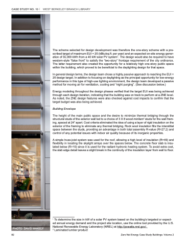
PHOTO: DAVID WAKELY
1 To determine the size in kW of a solar PV system based on the building’s targeted or expect- ed annual energy demand and the project site location, use the online tool provided by the U.S. National Renewable Energy Laboratory (NREL) at http://pvwatts.nrel.gov/.
2 Laminated lumber product
82
Zero Net Energy Case Study Buildings: Volume 2
