
Page 10 - ConnectorSupplier.com - How-to-Specify Handbook
P. 10
A Step-by-Step Guide for Rugged Connector Selection in the Era of Ever-Increasing Data Speed and Miniaturization Demands
By David Cianciolo, Engineering Director, Fischer Connectors, Inc.
Connector selection has morphed from the old standby, “How many contacts do you need?” into a much more serious challenge. Today’s design engineers need to nd ways to pump increasing amounts of data through smaller and smaller spaces, and usability experts now add their ideas into the mix as well. This creates additional challenges, such as guring out how to run both electrical and signal in a single connector and cable combination without interference, and alters the traditional, tried-and-true connector selection process.
Electrical Needs
Despite the changes that ever-increasing data speed and miniaturization demands have imposed on the rugged connector selection process, the rst step hasn’t changed because physics hasn’t changed. De ning the electrical voltage and current requirements for each contact is still the rst step to selecting ideal connectors for a given device. Specifying engineers have to ensure that they not only have the right number of contacts, but that the contacts can handle the power and signal demands of the application at hand. The size of the contacts and the size of the wire dictate the current-carrying capacity of a connector, while contact spacing, insulation materials, and the geometry of the insulator used to isolate the contacts dictates the voltage rating.
To ensure the design-in of the proper connector, engineers must dig into manufacturers’ test data to identify exactly how their testing was conducted and how their current rating and operating voltage speci cations were derived, as testing criteria can vary.
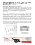
When reviewing current ratings, it’s important to take note of the temperature rise speci cation, which indicates how much heat will be dissipated at a speci c current value. It’s also important to con rm that the contact will support the selected conductor size, as a non-compatible conductor could cause overheating issues and lead to premature connector failure. (See Figure 1 and Table 1.)
Figure 1: The relationship between current and conductor size.
Table 1: *To identify the recommended current capacity, multiply the amperage value by this factor.
10
