
Page 4 - CAM product catalogue
P. 4
4
B FORKLIFT
CG B-S ATTACHMENT
CGc LL B-S LOAD
0. Introduction NOTE
All our equipment is standard supplied with FEM mounting class II A, III A or IV A.
Subsequently the dimensions of height, ground clearance, thickness, centre of gravity and weight refer to these classes. Moreover, in the event that these attachments will be tted to a lift truck with a di erent FEM-hook class, the shown values refer to the lighter class.
FEM class II B, III B or IV B can be provided on request at no surcharge.
Mounting types not included in the above categories are to be considered as special and are available only on request (at relative extra charge).
GENERAL INFORMATION
All the hydraulically operated equipment indicated here, with the exception of the sideshifter are standard tted with pre-regulated non-return and maximum pressure valves.
As the ow rate of oil supplied to the equipment is essential for the functioning of the same, it is advisable to use supply pipes, where possible, with an internal diameter of at least 10 mm up to a capacity of 2500 kg and of 12-13 mm for larger capacities. Elbows, connectors and throttled passages must be reduced to an absolute minimum.
The rotating attachments will be delivered with a built-in forward angle of 0°-2° on the truck’s carriage; 4° mounting upon request. Indicated capacities, dimensions and performance of the equipment are purely indicative, and in the interest of product development CAM S.r.l. reserves the right to make any modi cations without prior notice.
Stated capacities relate solely to the equipment.
In order to determine the residual capacity of the truck-equipment assembly, it is necessary to calculate the residual capacity as indicated. It is also necessary to remember that there are di erent variables such as the type of load concerned, working conditions of the truck, type of tyres, type of upright and relative lifting, all features which may a ect the residual working capacities and therefore must be duly considered and evaluated.
o. Introduction
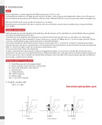
RESIDUAL CAPACITY CALCULATION
• • • • • • • •
X =
P = Truck lifting capacity to the required height
C = Centre of gravity to which the truck capacity refers B = Fork-carrier plate wheel centre distance
S = Fork thickness
LL = Clamp thickness
CG = Centre of gravity
K = Clamp weight
CGc = Load centre of gravity
P x (B+C) – K x [(B-S) + CG] [(B-S) + LL + CGc]
S P
C
See www.camsystem.com
K
