
Page 99 - NEW Armstrong Book - 2
P. 99
IGBT transistors are minority-carrier devices featuring high input impedance and large, bipolar current-carrying capability.
The inductive load characteris-
tics of motor control applications
often require the addition of an anti-
parallel or free-wheeling diode to
obtain a fully functional switch,
although in some special cases, the
free-wheeling diode is not necessary.
Placed in parallel with the power tran-
sistors, the free-wheeling diodes are
connected between the collector ter-
minal and the emitter terminal to con-
duct the reverse current. These diodes
come into play during switch-off, for
example, as an inductive load current
can generate high-voltage peaks if a
suitable path is not provided. This, in turn, could destroy the power switch. Due to its structure, the IGBT transistor does not have a parasitic diode as MOSFETs do. The free-wheeling diodes can be incorporated monolithically or added as a dis- crete diode external to the IGBT package.
The three-phase electric motor is the most common type of motor and can account for up to 60% of the entire power requirement of an industry.
When the lower-side free-wheeling diode is in reverse recovery, the direction of its current flow is the same as that of the upper-side switch, and vice versa; therefore, an over- shoot occurs on the turn-on commutation, which produces additional power loss, affecting the overall efficiency. SiC MOSFETs, thanks to much lower values of reverse-recovery current and shorter reverse-recovery times, allow a drastic reduction in recovery loss, with a marked improvement in efficiency compared with free-wheeling diodes co-packed with Si-based IGBTs.
Turn-on/turn-off commutation
requirements
In industrial drives, particular attention must be paid to turn- on and turn-off commutation speeds. Note that dV/dt in SiC MOSFETs can reach much higher levels than in IGBTs. If
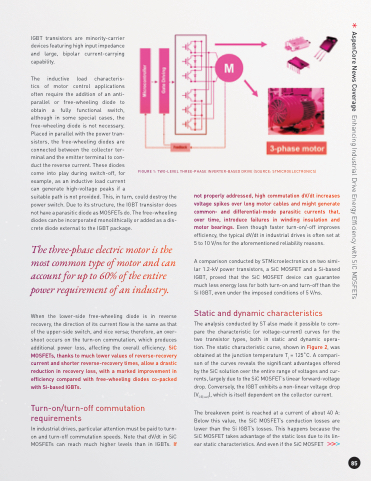
FIGURE 1: TWO-LEVEL THREE-PHASE INVERTER-BASED DRIVE (SOURCE: STMICROELECTRONICS)
not properly addressed, high commutation dV/dt increases voltage spikes over long motor cables and might generate common- and differential-mode parasitic currents that, over time, introduce failures in winding insulation and motor bearings. Even though faster turn-on/-off improves efficiency, the typical dV/dt in industrial drives is often set at 5 to 10 V/ns for the aforementioned reliability reasons.
A comparison conducted by STMicroelectronics on two simi- lar 1.2-kV power transistors, a SiC MOSFET and a Si-based IGBT, proved that the SiC MOSFET device can guarantee much less energy loss for both turn-on and turn-off than the Si IGBT, even under the imposed conditions of 5 V/ns.
Static and dynamic characteristics
The analysis conducted by ST also made it possible to com- pare the characteristic (or voltage-current) curves for the two transistor types, both in static and dynamic opera- tion. The static characteristic curve, shown in Figure 2, was obtained at the junction temperature Tj = 125˚C. A compari- son of the curves reveals the significant advantages offered by the SiC solution over the entire range of voltages and cur- rents, largely due to the SiC MOSFET’s linear forward-voltage drop. Conversely, the IGBT exhibits a non-linear voltage drop (VCE(sat)), which is itself dependent on the collector current.
The breakeven point is reached at a current of about 40 A: Below this value, the SiC MOSFET’s conduction losses are lower than the Si IGBT’s losses. This happens because the SiC MOSFET takes advantage of the static loss due to its lin- ear static characteristics. And even if the SiC MOSFET
85
AspenCore News Coverage Enhancing Industrial Drive Energy Efficiency with SiC MOSFETs
