


Page 239 - ToroProductCatalogue2016
P. 239
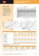
Valve Size Selection
Should be based on obtaining a
velocity that falls within the 0.5-5 m/ sec range. Velocity in the range 5-8 m/ sec is acceptable.* Valves with pressure reducing or sustaining pilots fitted operate effectively within the 0.5 -8 m/ sec range (0.5-5 m/sec best). Velocities outside the 0.5-8 m/sec range are not recommended.
*Risk of water hammer is increased. Precautions may be necessary to avoid potential damage.
Flow vs Head Loss Chart 50 mm
50 mm
80 mm
Velocity vs Flow Chart 100 mm
150 mm
Gulf Valves Control Functions and Operating Parameters
80/65/80
Flow Rate (m3/hr)
Dimensions and Weights
Valve Size
Length (mm)
Height (mm)
Hm* (mm)
Width (mm)
Radius (mm)
Mass (kg)
Inline Threaded Valves
*Hm – Height when valve fitted with optional mechanical throttle (in fully open position) Control Ports 1⁄4˝ and 1⁄2˝ BSP
50 mm
169
117
202
127
44
3.8
80/65/80 mm
230
154
239
145
59
7.0
Inline Flanged Valves
80 mm
242
202
342
203
102
19.6
100 mm
315
243
383
228
114
21.5
150 mm
403
331
N/A
305
153
54.6
Flow Factor Table
Valve Size
50 mm FBSP
80/65/80 FBSP
80 mm Flanged
100 mm Flanged
150 mm Flanged
k
0.00325
0.00116
0.00176
0.00146
0.000011
n
1.908
1.9556
1.7905
1.673
2.249
Equation: Headloss (H) = KQn k = head loss constant, n = head loss index, H = headloss in metres, Q = flow in m3/hr
Company policy is one of constant improvement and therefore changes in specifications may be made without notice and without incurring liability. Please refer to www.toro.com.au Toro Australia Pty Ltd, 53 Howards Road, Beverley, South Australia, 5009. Phone 1300 130 898, fax (08) 8243 2488. A.B.N. 47 001 310 443
239
Velocity (m/sec)


