


Page 315 - ToroProductCatalogue2016
P. 315
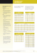
Calculating Control Valve Wiring Size
Method of Wire Sizing from controller to solenoid valve
Data Needed
• Inrush current of the solenoid valve (I)
• Distance in metres (one way) between controller and solenoid valve (D)
• The allowable voltage drop in the wire without affecting the operation of the solenoid valve (Vd)
Steps
1. Calculate the maximum allowable wire resistance per 1000 metres with the following formula:
R = 500* × Vd D× I
where R = allowable wire resistance per 1000 metres
* This assumes that the active and common wires are the same size
Example: A valve with a minimum operating voltage of 20 volts and an inrush current of 0.34 amps is to be located 650 metres from the controller. The controller minimum output voltage is 24 VAC.
The allowable voltage drop Vd = 24-20 = 4 volts
The distance to the valve (D) = 650 metres
The current draw (I) = 0.34 amps
R = 500 × 4 = 9.05 ohms/1000m 650 × 0.34
From Table 2, 1.5 mm2 wire has too much resistance, therefore select 2.5 mm2
Table 3 provides maximum wire runs given a solenoid valve with a minimum operating voltage of 20 volts AC, an inrush current of 0.34 amps and a controller minimum output voltage of 24 VAC.
For example, such a solenoid that was 810 metres away from the controller, could have a 2.5 mm2 active with a
4 mm2 common wire.
Company policy is one of constant improvement and therefore changes in specif Toro Australia Pty Ltd, 53 Howards Road, Beverley, South Australia, 5009. Phone
Table 4 provides multiplying factors should the minimum output voltage of the controller vary from the 24 VAC used in table 3.
For example, if the controller output is 26 VAC, the multiplying factor is 1.5. From table 3 the maximum distance for 1.5 mm2 active and common is 433 metres. If the controller minimum output is 26Vac the maximum distance is 433 × 1.5 = 649 metres.
Table 1
Minimum Operating Voltages at Various Mainline Pressures
Minimum Pressure (kPa)
Minimum Voltage (Internal Bleed)
Minimum Voltage (External Bleed)
1350
21.1
1200
20.2
1000
19.1
20.0
850
18.2
19.1
700
17.1
18.2
500
16.1
17.3
350
16.0
16.4
Table 2
Copper Wire Resistance
Nominal Area of Conductor (mm2)
Resistance at 20˚C ohms / 1000 m
0.5
38.4
1.0
21.2
1.5
13.6
2.5
7.4
4.0
4.6
6.0
3.1
10.0
1.8
16.0
1.1
Table 3
Maximum one-way distance between controller and valve
Common Wire (mm2)
Active Wire (mm2)
0.50
1.00
1.50
2.50
4.00
6.00
0.50
153
197
226
257
274
283
1.00
197
277
338
411
456
484
1.50
226
338
433
560
646
704
2.50
257
411
560
795
980
1120
4.00
274
456
646
980
1279
1528
6.00
283
484
704
1120
1528
1898
This table has been calculated based on the following factors. Solenoid voltage: 24VAC, Maximum Pressure: 1000 kPa, Voltage drop: 4 volts, Solenoid inrush current: 0.34 Amps.
Table 4
Multiplier Factor for Minimum Output Voltages from Controllers
Controller Output Voltage
24 VAC Solenoid
28
2.00
27
1.75
26
1.50
25
1.25
24
1.00
23
0.75
22
0.50
Table 5
American Wire Cross Sectional Area
AWG Gauge
Area (mm2)
AWG Gauge
Area (mm2)
26
0.128
12
3.302
25
0.162
11
4.156
24
0.205
10
5.271
23
0.255
9
6.629
22
0.322
8
8.350
21
0.411
7
10.544
20
0.516
6
13.292
19
0.653
5
16.755
18
0.823
4
21.137
17
1.039
3
26.653
16
1.308
2
33.606
15
1.652
1
42.384
14
2.088
0
53.454
13
2.629
00
67.399
ications may be made without notice and without incurring liability. Please refer to www.toro.com.au 1300 130 898, fax (08) 8243 2488. A.B.N. 47 001 310 443
315


