


Page 95 - ToroProductCatalogue2016
P. 95
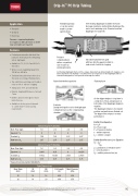
• Vineyards • Orchards • Row Crops
Pressure compensating dripline
for irrigation in difficult terrain or where long run lengths are required.
• Featuring an innovative turbulent flow path and chemically inert self-flushing silicon diaphragm.
• Available in 1.6, 2.0, 2.4 and 4.0 L/ h flow rates.
• Wide pressure regulating range from 100 kPa to 400 kPa.
• Turbulent flow path ensures there is no flow spike or prolonged flushing mode.
• Two outlet holes and large exit chamber reduces risk of exit hole clogging.
• Tubing sizes of 16, and 20 mm OD.
• Durable, tough wall thickness of at least 1 mm.
• Emitter cannot be dislodged or move inside the pipe.
• Available in factory spaced intervals or custom made to your spacing requirements.
Drip-InTM PC Drip Tubing
Application
Standard spacings or can be custom made to grower specifications.
Pressure compensating to deliver a regulated rate of water at varying pressures.
Raised inlet deflects particles
Contents
During the irrigation cycle, the diaphragm is depressed across the compensating chamber
Self-cleaning diaphragm chamber increases blockage resistance and facilitates flushing at the end of each watering cycle. Chemical resistant diaphragm for longer life.
Innovative turbulent flow path
with two directly opposed outlets to reduce risk of exit hole clogging.
Flushing Cycle
As the dripper begins to clog there is a reduction of flow, and pressure on both sides of the diaphragm begins to equalise.
The diaphragm returns to its relaxed position and particles are flushed out. The dripper then returns to normal performance
Emitter Flow Equation
Q = kpPx
Q = Flow in Lph
P = Pressure in metres x - emitter exponent
kp = emitter constant
Emitter Barb Pressure Loss Equation
Hb = kbv2 2g
g = gravitation acceleration m/sec2 v = velocity (m/sec)
Hb = emitter pressure loss (m)
Features
Self-flushing diaphragm flushes in three stages, being start-up, during irrigation if clogging occurs and on shut down. The flushing occurs where there is low pressure on the diaphragm and it is relaxed allowing particles to be passed out through the emitter.
Nom. Flow (Lph)
Exponent *, x
0
0
0
0
Constant, kp
1.56
1.82
2.25
3.67
Barb factor, kb
2.07
2.07
2.07
2.07
20mm Drip-In PC Emitter
Nom. Flow (Lph)
Exponent *, x
* Exponent determined within 100-400 kPa
Company policy is one of constant improvement and therefore changes in specif Toro Australia Pty Ltd, 53 Howards Road, Beverley, South Australia, 5009. Phone
16mm Drip-In PC Emitter
1.6
1.6
2.0
2.0
2.4
2.4
4.0
4.0
0.088
0.05
0
0.0256
Constant, kp
1.1432
1.6255
2.426
3.7638
Barb factor, kb
0.75
0.75
0.75
0.75
Tube Dimensions
Nom. Diam (mm)
ID (mm)
OD (mm)
Coil Length (m)
Maxm Pressure (kPa)
16
14
16
450
350
20
18
20
300
350
ications may be made without notice and without incurring liability. Please refer to www.toro.com.au 1300 130 898, fax (08) 8243 2488. A.B.N. 47 001 310 443
95


