
Page 23 - VTE JUNE
P. 23
that can be lifted to a desired height and
then released. The carriage table provides
the horizontal platform. The backrest of the seat is completely vertical, and incorporates
a four-point harness system. A foam pad is placed between the pelvis and the horizontal seat base. The aim was to use a rigid seat base for the tests to minimise variability in
the experiments. However, the high pulses generated between the dummy pelvis and the rigid seat base during the impact rendered this impractical. A foam interface was therefore used to pad the seat base to provide some protection to the pelvis of the ATD during the impact. The pad was an ethyl vinyl acetate (EVA) copolymer foam with a density of 400 kg/m3 and a thickness of 12 mm. This foam is commonly used in padding materials for various sports such as hockey pads.
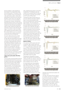
At impact, rubber pads provide a contact buffer to control the force applied to the carriage table which decelerates the carriage. The drop height combined with the selection of the type of rubber pad buffers influences the shape and properties of the pulse. Two rubber pads were placed in parallel on each individual block. The acceleration pulses applied to the carriage table of the drop
tower are shown in Figure 2. The height of the drop induces the required acceleration pulse to mimic the acceleration pulse experienced during a real land blast. A change in durometer of the rubber pad will alter the width and response of the system.
Lumbar spines and resultant ATD sitting position
The three lumbar spine assemblies used were the standard Hybrid III with the curved spine, the Hybrid III fitted with an FAA straight spine and FAA conversion kit, and the standard Hybrid III with a pedestrian lumbar spine
and base inserted. The FAA Hybrid III uses a different pelvis from the standard Hybrid III. It is essentially a standard Hybrid III, incorporating Hybrid II components such as the chest jacket, abdomen, upper legs, and the crucial pelvis and straight spine. The Hybrid III Pedestrian ATD is a standing ATD
with a straight spine that allows crash testing of pedestrians. The Pedestrian spine was inserted into the standard Hybrid III, replacing the curved spine. Importantly, during testing, each ATD used a different pelvis.
In testing three types of lumbar spines, the aim was to determine the effect of different types of commercially available lumbar spines and subsequently their induced lumbar load orientation. The two straight spine
ATDs maintained similar measurements for the H-point (the theoretical location of an occupant’s hip) to seat back. The angle of
the lumbar spine load cell of the Hybrid III
with the curved spine is 22∞ to the vertical. This increased the distance between the H-point and the seat back by 25 mm further. Furthermore, the curved spine causes the ATD to have a greater slouch. The taller lumbar spine of the FAA Hybrid III caused the ATD
to sit higher above the seat back than the other two ATDs. Figure 3 shows the different lumbar spines and load cells used in testing. Equipment Weights
Two variations of BBE masses were tested
to represent a light condition and a heavy condition. The light condition had a total mass of 17.7 kg and the heavy condition had a total mass of 30.3 kg. The FAA Hybrid III was the only ATD to be tested with both the light and heavy conditions due to timing constraints. The pedestrian lumbar spine and the curved spine lumbar assemblies were only tested without BBE and with heavy BBE.
The equipment configuration is shown in Figure 4. No equipment was placed directly on the back of the vest. However, a first aid kit and an accessory pouch were placed on the side and slightly to the rear of the vest.
A tri-axial accelerometer was attached to
a surrogate magazine mass for both the light and heavy conditions. This magazine mass was reduced by 50 grams so that the accelerometer could be placed inside the pouch of the vest unobstructed. The aim
of the accelerometer was to assess the loading of the total equipment mass. Figure
5 illustrates the accelerometer placed in the magazine mass.
Two tests were performed for the majority of conditions, with the aim of repeatability. Due to time constraints, only a single
test was performed for some of the FAA spine conditions. Two drop heights were investigated in order to achieve a registered dynamic response index (DRI) value of approximately 17.3 and 21.3. DRI is the measurement used to predict the probability
MEEA Lumber Spine | Feature
www.saea.com.au
VTE | 23
