
Page 10 - Bellofram Design Manual
P. 10
Class 3 Diaphragms
CLASS 3 DIAPHRAGMS
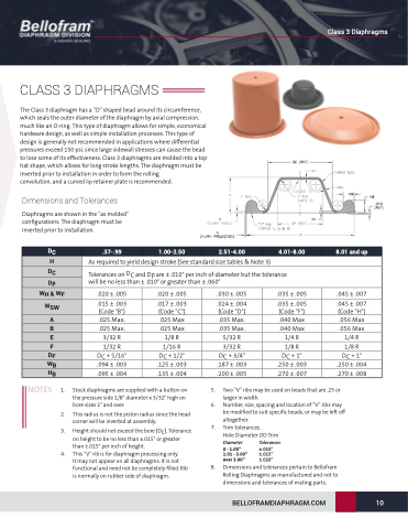
The Class 3 diaphragm has a “D” shaped bead around its circumference, which seals the outer diameter of the diaphragm by axial compression, much like an O-ring. This type of diaphragm allows for simple, economical hardware design, as well as simple installation processes. This type of design is generally not recommended in applications where differential pressures exceed 150 psi, since large sidewall stresses can cause the bead to lose some of its effectiveness. Class 3 diaphragms are molded into a top hat shape, which allows for long stroke lengths. The diaphragm must be inverted prior to installation in order to form the rolling
convolution, and a curved lip retainer plate is recommended.
Dimensions and Tolerances
Diaphragms are shown in the “as molded” configurations. The diaphragm must be inverted prior to installation.
As required to yield design stroke (See standard size tables & Note 3)
Tolerances on DC and Dp are ± .010" per inch of diameter but the tolerance will be no less than ± .010" or greater than ± .060"
DC
.37-.99
1.00-2.50
2.51-4.00
4.01-8.00
8.01 and up
H
DC
Dp
WH & WF
.020 ± .005
.015 ± .003 (Code "B") .025 Max.
.025 Max.
3/32 R
1/32 R
DC + 5/16" .094 ± .003
.095 ± .004
.020 ± .005
.017 ± .003 (Code "C") .025 Max
.025 Max
1/8 R
1/16 R
DC + 1/2" .125 ± .003
.135 ± .004
.030 ± .005
.024 ± .004 (Code "D") .035 Max.
.035 Max.
5/32 R
3/32 R
DC + 3/4" .187 ± .003
.200 ± .005
.035 ± .005
.035 ± .005 (Code "F") .040 Max
.040 Max
1/4 R
1/8 R
DC + 1" .250 ± .003
.270 ± .007
.045 ± .007
.045 ± .007 (Code "H") .056 Max
.056 Max
1/4 R
1/8 R
DC + 1" .250 ± .004
.270 ± .008
WSW
A
B
E
F
DF
WB
HB
NOTES 1.
2. This radius is not the piston radius since the head
corner will be inverted at assembly.
3. Height should not exceed the bore (DC). Tolerance on height to be no less than ±.015" or greater than ±.015" per inch of height.
4. This “V” rib is for diaphragm processing only.
It may not appear on all diaphragms. It is not functional and need not be completely filled. Rib is normally on rubber side of diaphragm.
5. Two “V” ribs may be used on beads that are .25 or larger in width.
6. Number, size, spacing and location of “V” ribs may be modified to suit specific beads, or may be left off altogether.
7. Trim tolerances.
Hole Diameter OD Trim
Stock diaphragms are supplied with a button on the pressure side 1/8" diameter x 3/32" high on bore sizes 1" and over.
Diameter
0 - 1.00” 1.01 - 3.00” over 3.00”
Tolerances
±.010” ±.015” ±.020”
8. Dimensions and tolerances pertain to Bellofram Rolling Diaphragms as manufactured and not to dimensions and tolerances of mating parts.
BELLOFRAMDIAPHRAGM.COM
10
