
Page 5 - Bellofram Design Manual
P. 5
Class 4 Diaphragms
CLASS 4 DIAPHRAGMS
The Class 4 diaphragm is the most common type of rolling diaphragm. This type of diaphragm has a flat flange, which is designed to act as a gasket between hardware with flat mating surfaces. The flat gasket design keeps the fabric reinforcement layer tightly clamped between the mating surfaces, enabling the diaphragm to seal against high pressures. The flange can be trimmed with slots and/or bolt holes to match almost any hardware configuration. The amount of clamping pressure necessary to achieve a good seal is generally on the order of 1000 psi, but this can vary by application. Class 4 diaphragms are molded into a top-hat shape, which allows for long stroke lengths. In order to form the rolling convolution, this type of diaphragm must be inverted prior to installation. It is recommended to use a curved lip retainer plate to keep the head corner of the diaphragm in contact with the piston and prevent re-inversion during operation.
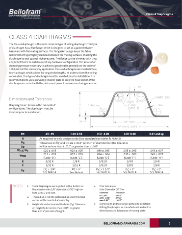
Dimensions and Tolerances
Diaphragms are shown in the “as molded” configurations. The diaphragm must be inverted prior to installation.
As required to yield design stroke (See standard size tables & Note 3)
Tolerances on DC and Dp are ± .010" per inch of diameter but the tolerance
DC
.25-.99
1.00-2.50
2.51-4.00
4.01-8.00
8.01 and up
H
DC
will be no less
.020 ± .005 .015 ± .003 (Code "B") 3/32 R
1/32 R
DC + 3/4" See Note 4
than ± .010" or greater than ± .060"
Dp
WH & WF
.020 ± .005 .017 ± .003 (Code "C") 1/8 R
1/16 R DC + 1" See Note 4
.030 ± .005 .024 ± .004 (Code "D") 5/32 R
3/32 R
DC + 1 1⁄2" See Note 4
.035 ± .005 .035 ± .005 (Code "F") 1/4 R
1/8 R
DC + 2" See Note 4
.045 ± .007 .045 ± .007 (Code "H") 1/4 R
1/8 R
DC + 2" See Note 4
WSW
E
F
DF
NOTES 1.
2. This radius is not the piston radius since the head
corner will be inverted at assembly.
3. Height should not exceed the bore (DC). Tolerance on height to be no less than ±.015" or greater than ±.015" per inch of height.
4. Trim tolerances.
Hole Diameter OD Trim
Stock diaphragms are supplied with a button on the pressure side 1/8" diameter x 3/32" high on bore sizes 1" and over.
Diameter
0 - 1.00” 1.01 - 3.01” over 3.01”
Tolerances
±.010” ±.015” ±.020”
5. Dimensions and tolerances pertain to Bellofram Rolling Diaphragms as manufactured and not to dimensions and tolerances of mating parts.
BELLOFRAMDIAPHRAGM.COM
5
