
Page 10 - Aqualife Steam Steriliser Water Systems
P. 10
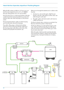
Steam Steriliser Operation; AquaClave® Plumbing Diagram
When the RO system is installed a 1/2” brass tee is cut into the water supply line and a 1/2” to 1/4” 500kPA Pressure Limiting Valve and a 1/4” stop tap  tted.
The 1/4” plastic hose is connected and leads to the inlet on the front of the 1st Housing which has a plastic tee with the other side of the tee going to a low pressure switch.
The hose from the elbow at the rear of this housing runs from the inlet solenoid to the pump.
Water passes through the membrane to 2 outlets in the housing.
1. One leads to a tee and through a High Pressure Switch to the inlet of the Zapper and the other side of the tee goes to the tank.
2. The other outlet is the reject water to the drain via a 400 Flow Restrictor.
The Flush Solenoid allows a diversion around this Flow Restrictor when the system is in  ush mode.
The outlet of the pWumpPis a5ttac0he0d to7theAelbQow U
at the rear of the 2nd housing with the outlet from
The Product Water passes through the Zapper to the inlet at the front of the 3rd housing. From the elbow
this housing going
membrane housing (the end with the cap).
e
to th
ee
lbo
wo
n th
e in
at the rear of this housing, Product Water goes to the
let o
ACLAVE MARK III
f th
PLUMBING DIAGRAM
Faucet and/or Autoclave.
When the tank is full, the system automatically shuts down until Product Water is required and  rst  ushes to the drain thus clearing the membrane of fouling material.
TAP
TANK
PRESSURE HIGH SWITCH
ZAPPER
FLOW RESTRICTOR 400
FLUSHING SOLENOID
TO DRAIN
MEMBRANE
PRESSURE LOW SWITCH
500 KPA PLV
TO FAUCET AUTOCLAVE
3RD 2ND HOUSING HOUSING
ELBOW 1ST HOUSING
PUMP
INLET SOLENOID
TRANSFORMER
10
OUT
IN
OUT
IN
IN
TEE
TAP
BRASS TCL
OUT
IN
REJECT WATER
TEE
