
Page 1044 - College Physics For AP Courses
P. 1044
1032 Chapter 23 | Electromagnetic Induction, AC Circuits, and Electrical Technologies
As we have seen, any change in magnetic flux induces an emf opposing that change—a process known as induction. Motion is one of the major causes of induction. For example, a magnet moved toward a coil induces an emf, and a coil moved toward a magnet produces a similar emf. In this section, we concentrate on motion in a magnetic field that is stationary relative to the Earth, producing what is loosely called motional emf.
One situation where motional emf occurs is known as the Hall effect and has already been examined. Charges moving in a magnetic field experience the magnetic force � � ��� ��� � , which moves opposite charges in opposite directions and
produces an ��� � ��� . We saw that the Hall effect has applications, including measurements of � and � . We will now see that the Hall effect is one aspect of the broader phenomenon of induction, and we will find that motional emf can be used as a
power source.
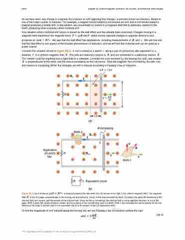
Consider the situation shown in Figure 23.11. A rod is moved at a speed � along a pair of conducting rails separated by a distance � in a uniform magnetic field � . The rails are stationary relative to � and are connected to a stationary resistor � .
The resistor could be anything from a light bulb to a voltmeter. Consider the area enclosed by the moving rod, rails, and resistor. � is perpendicular to this area, and the area is increasing as the rod moves. Thus the magnetic flux enclosed by the rails, rod,
and resistor is increasing. When flux changes, an emf is induced according to Faraday’s law of induction.
Figure 23.11 (a) A motional ��� � ��� is induced between the rails when this rod moves to the right in the uniform magnetic field. The magnetic field � is into the page, perpendicular to the moving rod and rails and, hence, to the area enclosed by them. (b) Lenz’s law gives the directions of the
induced field and current, and the polarity of the induced emf. Since the flux is increasing, the induced field is in the opposite direction, or out of the page. RHR-2 gives the current direction shown, and the polarity of the rod will drive such a current. RHR-1 also indicates the same polarity for the rod. (Note that the script E symbol used in the equivalent circuit at the bottom of part (b) represents emf.)
To find the magnitude of emf induced along the moving rod, we use Faraday’s law of induction without the sign:
��� � ���� (23.7)
�� This OpenStax book is available for free at http://cnx.org/content/col11844/1.14
