
Page 937 - College Physics For AP Courses
P. 937
Chapter 21 | Circuits, Bioelectricity, and DC Instruments 925
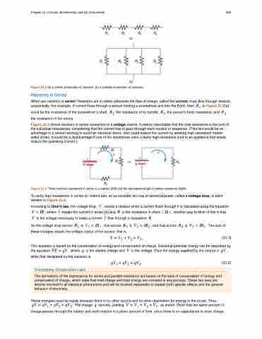
Figure 21.2 (a) A series connection of resistors. (b) A parallel connection of resistors. Resistors in Series
When are resistors in series? Resistors are in series whenever the flow of charge, called the current, must flow through devices sequentially. For example, if current flows through a person holding a screwdriver and into the Earth, then �� in Figure 21.2(a)
could be the resistance of the screwdriver’s shaft, �� the resistance of its handle, �� the person’s body resistance, and �� the resistance of her shoes.
Figure 21.3 shows resistors in series connected to a voltage source. It seems reasonable that the total resistance is the sum of the individual resistances, considering that the current has to pass through each resistor in sequence. (This fact would be an advantage to a person wishing to avoid an electrical shock, who could reduce the current by wearing high-resistance rubber- soled shoes. It could be a disadvantage if one of the resistances were a faulty high-resistance cord to an appliance that would reduce the operating current.)
Figure 21.3 Three resistors connected in series to a battery (left) and the equivalent single or series resistance (right).
To verify that resistances in series do indeed add, let us consider the loss of electrical power, called a voltage drop, in each
resistor in Figure 21.3.
According to Ohm’s law, the voltage drop, � , across a resistor when a current flows through it is calculated using the equation
� � �� , where � equals the current in amps (A) and � is the resistance in ohms � � � . Another way to think of this is that � is the voltage necessary to make a current � flow through a resistance � .
So the voltage drop across �� is �� � ��� , that across �� is �� � ��� , and that across �� is �� � ��� . The sum of these voltages equals the voltage output of the source; that is,
� � �� � �� � ��� (21.1) This equation is based on the conservation of energy and conservation of charge. Electrical potential energy can be described by
the equation �� � �� , where � is the electric charge and � is the voltage. Thus the energy supplied by the source is �� , while that dissipated by the resistors is
��� � ��� � ���� (21.2)
These energies must be equal, because there is no other source and no other destination for energy in the circuit. Thus,
�� � ��� � ��� � ��� . The charge � cancels, yielding � � �� � �� � �� , as stated. (Note that the same amount of charge passes through the battery and each resistor in a given amount of time, since there is no capacitance to store charge,
Connections: Conservation Laws
The derivations of the expressions for series and parallel resistance are based on the laws of conservation of energy and conservation of charge, which state that total charge and total energy are constant in any process. These two laws are directly involved in all electrical phenomena and will be invoked repeatedly to explain both specific effects and the general behavior of electricity.
