
Page 116 - Physics Coursebook 2015 (A level)
P. 116
Cambridge International AS Level Physics
104
Compressive and tensile forces
A pair of forces is needed to change the shape of a spring. If the spring is being squashed and shortened, we say that the forces are compressive. More usually, we are concerned with stretching a spring, in which case the forces are described as tensile (Figure 7.4).
a b
compressive forces
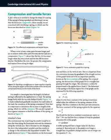
extension load
Figure 7.6 Stretching a spring.
force
A
c tensile forces
Figure 7.4 The effects of compressive and tensile forces.
When a wire is bent, some parts become longer and are in tension while other parts become shorter and are in compression. Figure 7.5 shows that the line AA becomes longer when the wire is bent and the line BB becomes shorter. The thicker the wire, the greater the compression and tension forces along its edges.
AA BB
gradient = k
0
Figure 7.7 Force–extension graph for a spring.
axis and force on the vertical axis. This is a departure from the convention because the gradient of the straight section of this graph turns out to be an important quantity, known as the force constant of the spring. For a typical spring, the first section of this graph OA is a straight line passing through the origin. The extension x is directly proportional to the applied force (load) F. The behaviour of the spring in the linear region OA of the graph can be expressed by the following equation:
x∝F or F = kx
where k is the force constant of the spring (sometimes called either the stiffness or the spring constant of the spring). The force constant is the force per unit extension. The force constant k of the spring is given by the equation:
k = Fx
The SI unit for the force constant is newtons per metre or N m−1. We can find the force constant k from the gradient of section OA of the graph:
k = gradient
A stiffer spring will have a larger value for the force constant k. Beyond point A, the graph is no longer a straight line; its gradient changes and we can no longer use the equation F = kx.
0
Extension, x
A B
A
Figure 7.5 Bending a straight wire or beam results in tensile forces along the upper surface (the outside of the bend) and compressive forces on the inside of the bend.
It is simple to investigate how the length of a helical spring is affected by the applied force or load. The spring hangs freely with the top end clamped firmly (Figure 7.6). A load is added and gradually increased. For each value of the load, the extension of the spring is measured. Note that it is important to determine the increase in length of the spring, which we call the extension. We can plot a graph of force against extension to find the stiffness of the spring, as shown in Figure 7.7.
Hooke’s law
The conventional way of plotting the results would be to have the force along the horizontal axis and the extension along the vertical axis. This is because we are changing the force (the independent variable) and this results in
a change in the extension (the dependent variable). The graph shown in Figure 7.7 has extension on the horizontal
B
Force, F
