
Page 146 - Physics Coursebook 2015 (A level)
P. 146
Cambridge International AS Level Physics
134
The potential difference between two points, A and B, is the energy per unit charge as charge moves from point A to point B.
e.m.f. is defined as the total work done per unit charge when charge flows round a complete circuit.
It may help you to picture how the drift velocity of electrons changes by thinking about the flow of water in
a river. For a high rate of flow, the water moves fast – this corresponds to a greater current I. If the course of the river narrows, it speeds up – this corresponds to a smaller cross- sectional area A.
Metals have a high electron number density – typically of the order of 1028 or 1029 m−3. Semiconductors, such as silicon and germanium, have much lower values of n – perhaps 1023 m−3. In a semiconductor, electron mean drift velocities are typically a million times greater than those in metals for the same current. Electrical insulators, such as rubber and plastic, have very few conduction electrons per unit volume to act as charge carriers.
The meaning of voltage
The term voltage is often used in a rather casual way.
In everyday life, the word is used in a less scientific and often incorrect sense – for example, ‘A big voltage can go through you and kill you.’ In this section, we will consider a bit more carefully just what we mean by voltage and potential difference in relation to electric circuits.
Look at the simple circuit in Figure 9.11. Assume
the power supply has negligible internal resistance. (We look at internal resistance later in Chapter 11). The three voltmeters are measuring three voltages or potential differences. With the switch open, the voltmeter placed across the supply measures 12V. With the switch closed, the voltmeter across the power supply still measures 12 V and the voltmeters placed across the resistors measure 8 V and 4 V. You will not be surprised to see that the voltage across the power supply is equal to the sum of the voltages across the resistors.
Earlier in this chapter we saw that electric current is the rate of flow of electric charge. Figure 9.12 shows the
V = 12 V V
12 V
R=20Ω R=10Ω VV
V= 8 V V= 4 V
Figure 9.11 Measuring voltages in a circuit. Note that each voltmeter is connected across the component.
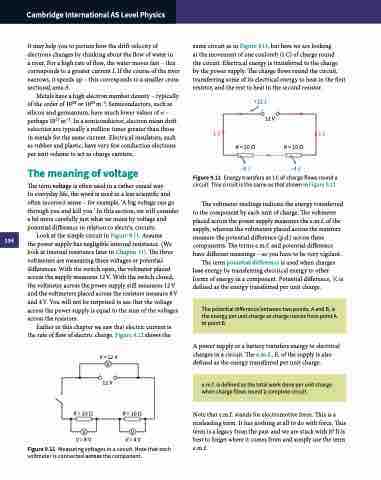
same circuit as in Figure 9.11, but here we are looking
at the movement of one coulomb (1 C) of charge round
the circuit. Electrical energy is transferred to the charge by the power supply. The charge flows round the circuit, transferring some of its electrical energy to heat in the first resistor, and the rest to heat in the second resistor.
+12 J
12 V
1C
1C
R = 20 Ω –8 J
R = 10 Ω –4 J
Figure 9.12 Energy transfers as 1 C of charge flows round a circuit. This circuit is the same as that shown in Figure 9.11.
The voltmeter readings indicate the energy transferred to the component by each unit of charge. The voltmeter placed across the power supply measures the e.m.f. of the supply, whereas the voltmeters placed across the resistors measure the potential difference (p.d.) across these components. The terms e.m.f. and potential difference have different meanings – so you have to be very vigilant.
The term potential difference is used when charges lose energy by transferring electrical energy to other forms of energy in a component. Potential difference, V, is defined as the energy transferred per unit charge.
A power supply or a battery transfers energy to electrical charges in a circuit. The e.m.f., E, of the supply is also defined as the energy transferred per unit charge.
Note that e.m.f. stands for electromotive force. This is a misleading term. It has nothing at all to do with force. This term is a legacy from the past and we are stuck with it! It is best to forget where it comes from and simply use the term e.m.f.
