
Page 157 - Physics Coursebook 2015 (A level)
P. 157
Chapter 10: Kirchhoff’s laws
QUESTIONS
1 Use Kirchhoff’s first law to deduce the value of the current I in Figure 10.4.
3.0 A
7.5 A
I
Figure 10.4 For Question 1.
2 In Figure 10.5, calculate the current in the wire X. State the direction of this current (towards P or away from P).
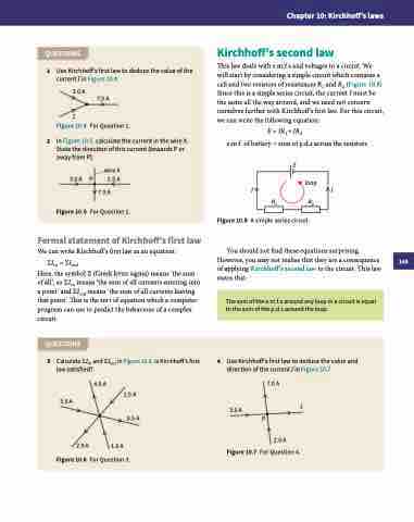
Kirchhoff’s second law
This law deals with e.m.f.s and voltages in a circuit. We will start by considering a simple circuit which contains a cell and two resistors of resistances R1 and R2 (Figure 10.8). Since this is a simple series circuit, the current I must be the same all the way around, and we need not concern ourselves further with Kirchhoff’s first law. For this circuit, we can write the following equation:
E = IR1 + IR2
e.m.f. of battery = sum of p.d.s across the resistors
E
loop
II R1 R2
Figure 10.8 A simple series circuit.
You should not find these equations surprising. However, you may not realise that they are a consequence of applying Kirchhoff’s second law to the circuit. This law states that:
wire X 2.5 A
7.0 A
Figure 10.5 For Question 2.
Formal statement of Kirchhoff’s first law
We can write Kirchhoff’s first law as an equation:
ΣIin = ΣIout
Here, the symbol Σ (Greek letter sigma) means ‘the sum of all’, so ΣIin means ‘the sum of all currents entering into a point’ and ΣIout means ‘the sum of all currents leaving that point’. This is the sort of equation which a computer program can use to predict the behaviour of a complex circuit.
QUESTIONS
3 Calculate ΣIin and ΣIout in Figure 10.6. Is Kirchhoff’s first law satisfied?
3.0 A P
2.0 A
1.0 A
Figure 10.6 For Question 3.
4.0 A
7.0 A
4
Use Kirchhoff’s first law to deduce the value and direction of the current I in Figure 10.7.
The sum of the e.m.f.s around any loop in a circuit is equal to the sum of the p.d.s around the loop.
3.0 A
2.5 A 0.5 A
I
Figure 10.7 For Question 4.
3.0 A
2.0 A
P
145
