
Page 210 - Physics Coursebook 2015 (A level)
P. 210
Cambridge International AS Level Physics
BOX 14.3: Interference of radiation
198
screen
slide with double slit
amplitudes but are in phase (Figure 14.14c), constructive interference results in a wave whose amplitude is the sum of the two individual amplitudes.
QUESTION
3 Explain why the two loudspeakers must produce sounds of precisely the same frequency if we are to hear the effects of interference.
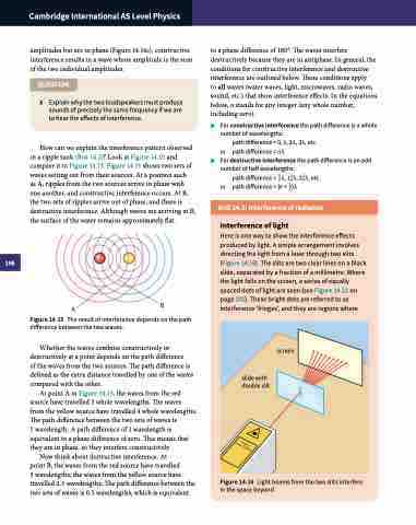
How can we explain the interference pattern observed in a ripple tank (Box 14.2)? Look at Figure 14.15 and compare it to Figure 14.13. Figure 14.15 shows two sets of waves setting out from their sources. At a position such
as A, ripples from the two sources arrive in phase with one another, and constructive interference occurs. At B, the two sets of ripples arrive out of phase, and there is destructive interference. Although waves are arriving at B, the surface of the water remains approximately flat.
to a phase difference of 180°. The waves interfere destructively because they are in antiphase. In general, the conditions for constructive interference and destructive interference are outlined below. These conditions apply
to all waves (water waves, light, microwaves, radio waves, sound, etc.) that show interference effects. In the equations below, n stands for any integer (any whole number, including zero).
■■
■■
For constructive interference the path difference is a whole number of wavelengths:
path difference = 0, λ, 2λ, 3λ, etc. or path difference = nλ
For destructive interference the path difference is an odd number of half wavelengths:
path difference = 12 λ, 112 λ, 212 λ, etc. or path difference = (n + 12 )λ
Interference of light
Here is one way to show the interference effects produced by light. A simple arrangement involves directing the light from a laser through two slits (Figure 14.16). The slits are two clear lines on a black slide, separated by a fraction of a millimetre. Where the light falls on the screen, a series of equally spaced dots of light are seen (see Figure 14.21 on page 201). These bright dots are referred to as interference ‘fringes’, and they are regions where
A
B
Figure 14.15 The result of interference depends on the path difference between the two waves.
Whether the waves combine constructively or destructively at a point depends on the path difference
of the waves from the two sources. The path difference is defined as the extra distance travelled by one of the waves compared with the other.
At point A in Figure 14.15, the waves from the red source have travelled 3 whole wavelengths. The waves from the yellow source have travelled 4 whole wavelengths. The path difference between the two sets of waves is
1 wavelength. A path difference of 1 wavelength is equivalent to a phase difference of zero. This means that they are in phase, so they interfere constructively.
Now think about destructive interference. At
point B, the waves from the red source have travelled
3 wavelengths; the waves from the yellow source have travelled 2.5 wavelengths. The path difference between the two sets of waves is 0.5 wavelengths, which is equivalent
Figure 14.16 Light beams from the two slits interfere in the space beyond.
