
Page 213 - Physics Coursebook 2015 (A level)
P. 213
Chapter 14: Superposition of waves
laser
double slit interference in this region
Figure 14.20 Interference occurs where diffracted beams from the two slits overlap.
Figure 14.21 Interference fringes obtained using a laser and a double slit.
sets of waves, and the pattern of fringes on the screen shows us the result of their interference (Figure 14.21).
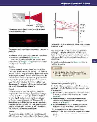
How does this pattern arise? We will consider three points on the screen (Figure 14.22), and work out what we would expect to observe at each.
Point A
This point is directly opposite the midpoint of the slits.
Two rays of light arrive at A, one from slit 1 and the other from slit 2. Point A is equidistant from the two slits, and so the two rays of light have travelled the same distance. The path difference between the two rays of light is zero. If we assume that they were in phase (in step) with each other when they left the slits, then they will be in phase when they arrive at A. Hence they will interfere constructively, and we will observe a bright fringe at A.
Point B
This point is slightly to the side of point A, and is the
midpoint of the first dark fringe. Again, two rays of light arrive at B, one from each slit. The light from slit 1 has to travel slightly further than the light from slit 2, and so the two rays are no longer in step. Since point B is at the midpoint of the dark fringe, the two rays must be in antiphase (phase difference of 180°). The path difference between the two rays of light must be half a wavelength and so the two rays interfere destructively.
Point C
This point is the midpoint of the next bright fringe, with AB = BC. Again, ray 1 has travelled further than ray 2; this
1
a D
2
double slit
Figure 14.22 Rays from the two slits travel different distances to reach the screen.
time, it has travelled an extra distance equal to a whole wavelength λ. The path difference between the rays of light is now a whole wavelength. The two rays are in phase at the screen. They interfere constructively and we see a bright fringe.
The complete interference pattern (Figure 14.21) can be explained in this way.
QUESTION
6 Consider points D and E on the screen, where BC = CD = DE. State and explain what you would expect to observe at D and E.
Determining wavelength λ
The double-slit experiment can be used to determine the
wavelength λ of light. The following three quantities have to be measured:
■■ Slit separation a – This is the distance between the centres of the slits, which is the distance between slits 1 and 2 in Figure 14.22.
■■ Fringe separation x – This is the distance between the centres of adjacent bright (or dark) fringes, which is the distance AC in Figure 14.22.
■■ Slit-to-screen distance D – This is the distance from the midpoint of the slits to the central fringe on the screen.
Once these three quantities have been measured, the wavelength λ of the light can be found using the relationship:
λ = ax D
x
A bright B dark C bright D
E screen
201
