
Page 216 - Physics Coursebook 2015 (A level)
P. 216
Cambridge International AS Level Physics
n=–2
n=–1
n=0
θ n=+1
diffraction grating
n=+2
204
thousands of equally spaced lines of microscopic pits on its surface; these carry the digital information. It is the diffraction from these lines that produces the coloured bands of light from the surface of the CD.
Observing diffraction with a transmission grating
In Figure 14.25, monochromatic light from a laser is incident normally on a transmission diffraction grating. In the space beyond, interference fringes are formed. These can be observed on a screen, as with the double slit. However, it is usual to measure the angle θ at which they are formed, rather than measuring their separation. With double slits, the fringes are equally spaced and the angles are very small. With a diffraction grating, the angles are much greater and the fringes are not equally spaced.
The fringes are also referred to as maxima. The central fringe is called the zeroth-order maximum, the next fringe is the first-order maximum, and so on. The pattern is symmetrical, so there are two first-order maxima, two second-order maxima, and so on.
screen
Figure 14.25 The diffracted beams form a symmetrical pattern on either side of the undiffracted central beam.
Explaining the experiment
The principle is the same as for the double-slit experiment, but here we have light passing through many slits. As it passes through each slit, it diffracts into the space beyond. So now we have many overlapping beams of light, and these interfere with one another. It is difficult to achieve constructive interference with many beams, because they all have to be in phase with one another.
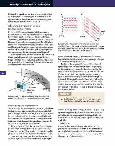
There is a bright fringe, the zeroth-order maximum, in the straight-through direction (θ = 0) because all of the rays here are travelling parallel to one another and in phase, so the interference is constructive (Figure 14.26a).
Imagine if you could look through the grating at the source of light. Your eye would be focused on the light
ab
grating grating
ray 6 ray 5
ray 4 ray 3
ray 2 ray 1
Figure 14.26 a Waves from each slit are in phase in the straight-through direction. b In the direction of the first-order maximum, the waves are in phase, but each one has travelled one wavelength further than the one below it.
source, which is far away. All the rays with θ = 0 come together at the back of your eye, where an image is formed. It is here that interference occurs.
The first-order maximum forms as follows. Rays of light emerge from all of the slits; to form a bright fringe, all the rays must be in phase. In the direction of the first- order maximum, ray 1 has travelled the smallest distance (Figure 14.26b). Ray 2 has travelled an extra distance equal to one whole wavelength and is therefore in phase with ray 1. The path difference between ray 1 and ray 2 is equal to one wavelength λ. Ray 3 has travelled two extra wavelengths and is in phase with rays 1 and 2. In fact, the rays from all of the slits are in step in this direction, and a bright fringe results.
QUESTION
11 Explain how the second-order maximum arises. Use the term path difference in your explanation.
Determining wavelength λ with a grating By measuring the angles at which the maxima occur, we can determine the wavelength of the incident light. The wavelength λ of the monochromatic light is related to the angle θ by:
dsinθ = nλ
where d is the distance between adjacent lines of the grating and n is known as the order of the maximum; n can only have integer values 0, 1, 2, 3, etc. The distance d is known as the grating element or grating spacing. This is illustrated in Worked example 2.
