
Page 386 - Physics Coursebook 2015 (A level)
P. 386
Cambridge International A Level Physics
The capacitance of a capacitor is the charge stored on one plate per unit of potential difference between the plates.
374
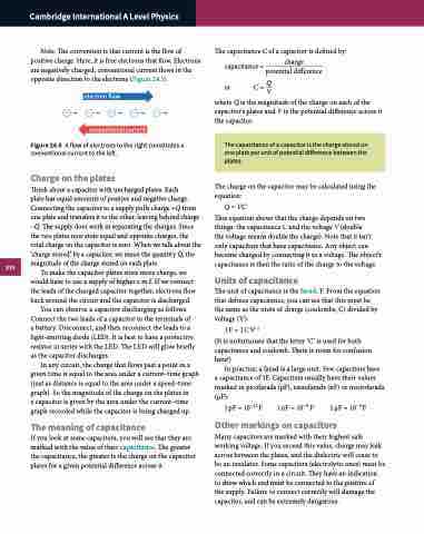
Note: The convention is that current is the flow of positive charge. Here, it is free electrons that flow. Electrons are negatively charged; conventional current flows in the opposite direction to the electrons (Figure 24.5).
electron flow conventional current
Figure 24.5 A flow of electrons to the right constitutes a conventional current to the left.
Charge on the plates
Think about a capacitor with uncharged plates. Each
plate has equal amounts of positive and negative charge. Connecting the capacitor to a supply pulls charge +Q from one plate and transfers it to the other, leaving behind charge –Q. The supply does work in separating the charges. Since the two plates now store equal and opposite charges, the total charge on the capacitor is zero. When we talk about the ‘charge stored’ by a capacitor, we mean the quantity Q, the magnitude of the charge stored on each plate.
To make the capacitor plates store more charge, we would have to use a supply of higher e.m.f. If we connect the leads of the charged capacitor together, electrons flow back around the circuit and the capacitor is discharged.
You can observe a capacitor discharging as follows. Connect the two leads of a capacitor to the terminals of a battery. Disconnect, and then reconnect the leads to a light-emitting diode (LED). It is best to have a protective resistor in series with the LED. The LED will glow briefly as the capacitor discharges.
In any circuit, the charge that flows past a point in a given time is equal to the area under a current–time graph (just as distance is equal to the area under a speed–time graph). So the magnitude of the charge on the plates in
a capacitor is given by the area under the current–time graph recorded while the capacitor is being charged up.
The meaning of capacitance
If you look at some capacitors, you will see that they are marked with the value of their capacitance. The greater the capacitance, the greater is the charge on the capacitor plates for a given potential difference across it.
The capacitance C of a capacitor is defined by: capacitance = charge
potential difference o r C = QV
where Q is the magnitude of the charge on each of the capacitor's plates and V is the potential difference across it the capacitor.
The charge on the capacitor may be calculated using the equation:
Q = VC
This equation shows that the charge depends on two things: the capacitance C and the voltage V (double
the voltage means double the charge). Note that it isn’t only capacitors that have capacitance. Any object can become charged by connecting it to a voltage. The object’s capacitance is then the ratio of the charge to the voltage.
Units of capacitance
The unit of capacitance is the farad, F. From the equation that defines capacitance, you can see that this must be the same as the units of charge (coulombs, C) divided by voltage (V):
1F = 1CV−1
(It is unfortunate that the letter ‘C’ is used for both capacitance and coulomb. There is room for confusion here!)
In practice, a farad is a large unit. Few capacitors have a capacitance of 1F. Capacitors usually have their values marked in picofarads (pF), nanofarads (nF) or microfarads (μF):
1pF = 10−12F 1nF = 10−9 F 1μF = 10−6F
Other markings on capacitors
Many capacitors are marked with their highest safe working voltage. If you exceed this value, charge may leak across between the plates, and the dielectric will cease to be an insulator. Some capacitors (electrolytic ones) must be connected correctly in a circuit. They have an indication
to show which end must be connected to the positive of the supply. Failure to connect correctly will damage the capacitor, and can be extremely dangerous.
