
Page 423 - Physics Coursebook 2015 (A level)
P. 423
Chapter 26: Magnetic fields and electromagnetism
Magnetic flux density
In electric or gravitational field diagrams, the strength
of the field is indicated by the separation between the
field lines. The field is strongest where the field lines are closest together. The same is true for magnetic fields. The strength of a magnetic field is known as its magnetic flux density, with symbol B. (You can imagine this quantity
to represent the number of magnetic field lines passing through a region per unit area.) The magnetic flux density is greater close to the pole of a bar magnet, and gets smaller as you move away from it.
We define gravitational field strength g at a point as the force per unit mass:
g = mF
Electric field strength E is defined as the force per unit
positive charge: E=F
The force on the conductor is given by the equation: F = BIL
Note that you can only use this equation when the field is at right angles to the current.
QUESTIONS
Q
b What force acts on the wire? Measuring magnetic flux
density
Box 26.2 looks at two practical methods for measuring magnetic flux density.
BOX 26.2: Measuring magnetic flux density
Measuring B with a Hall probe
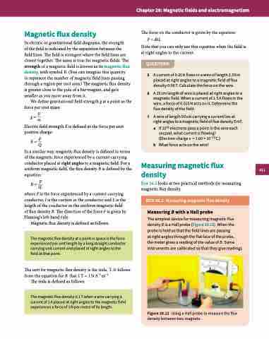
The simplest device for measuring magnetic flux density B is a Hall probe (Figure 26.12). When the probe is held so that the field lines are passing
at right angles through the flat face of the probe,
the meter gives a reading of the value of B. Some instruments are calibrated so that they give readings
In a similar way, magnetic flux density is defined in terms of the magnetic force experienced by a current-carrying conductor placed at right angles to a magnetic field. For a uniform magnetic field, the flux density B is defined by the equation:
B=F IL
where F is the force experienced by a current-carrying conductor, I is the current in the conductor and L is the length of the conductor in the uniform magnetic field of flux density B. The direction of the force F is given by Fleming’s left-hand rule.
Magnetic flux density is defined as follows:
The unit for magnetic flux density is the tesla, T. It follows from the equation for B that 1T = 1NA−1 m−1.
The tesla is defined as follows:
5 6
7
A current of 0.20 A flows in a wire of length 2.50 m placed at right angles to a magnetic field of flux density 0.06 T. Calculate the force on the wire.
A 20 cm length of wire is placed at right angles to a magnetic field. When a current of 1.5 A flows in the wire, a force of 0.015 N acts on it. Determine the flux density of the field.
A wire of length 50 cm carrying a current lies at right angles to a magnetic field of flux density 5 mT.
a If 1018 electrons pass a point in the wire each second, what current is flowing?
(Electron charge e = 1.60 × 10⁻¹⁹ C.)
The magnetic flux density at a point in space is the force experienced per unit length by a long straight conductor carrying unit current and placed at right angles to the field at that point.
The magnetic flux density is 1 T when a wire carrying a current of 1 A placed at right angles to the magnetic field experiences a force of 1 N per metre of its length.
Figure 26.12 Using a Hall probe to measure the flux density between two magnets.
411
