
Page 426 - Physics Coursebook 2015 (A level)
P. 426
Cambridge International A Level Physics
WORKED EXAMPLE
WORKED EXAMPLE
414
1 An electric motor has a rectangular loop of wire with the dimensions shown in Figure 26.19. The loop is in a magnetic field of flux density 0.10 T. The current in the loop is 2.0 A. Calculate the torque that acts on the loop in the position shown.
Step1 Thequantitiesweknoware: B=0.10T, I=2.0A andL=0.05m
Step2 Nowwecancalculatetheforceononesideof the loop using the equation F = BIL:
F=0.10×2.0×0.05 =0.01N
Step3 Thetwoforcesonoppositesidesoftheloop
are equal and anti-parallel. In other words, they form a couple. From Chapter 4, you should recall that the torque (moment) of a couple is equal to the magnitude of one
of the forces times the perpendicular distance between them. The two forces are separated by 0.08 m, so:
torque = force × separation
= 0.01 × 0.08 = 8.0 × 10⁻⁴ N m
2 A conductor OC (see Figure 26.20) of length 0.20 m lies at an angle θ of 25° to a magnetic field of flux density 0.050 T. Calculate the force on the conductor when it carries a current of 400 mA.
Step1 Writedownwhatyouknow,andwhatyou want to know:
B = 0.050T L = 0.20m I=400mA=0.40A θ=25° F=?
Step2 Writedowntheequation,substitutevalues and solve:
F = BIL sin θ
F =0.050×0.40×0.20×sin25°≈1.7×10⁻³N
Step3 Givethedirectionoftheforce.Theforceacts at 90° to the field and the current, i.e. perpendicular to the page. The left-hand rule shows that it acts downwards into the plane of the paper.
Note that the component of B parallel to the current is B cos θ, but this does not contribute to the force; there is no force when the field and current are parallel. The force F is at right angles to both the current and the field.
B = 0.10 T
F I = 2.0 A
0.08 m
F
0.05 m
Figure 26.19 A simple electric motor – a current- carrying loop in a magnetic field.
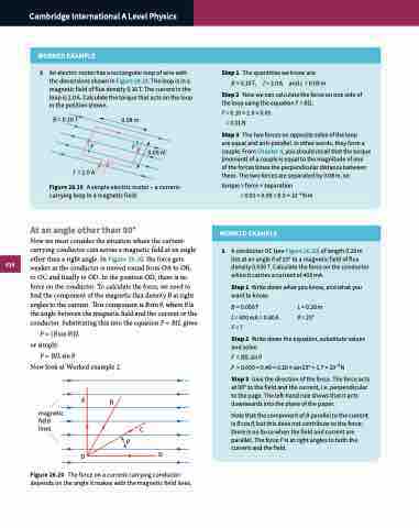
At an angle other than 90°
Now we must consider the situation where the current- carrying conductor cuts across a magnetic field at an angle other than a right angle. In Figure 26.20, the force gets weaker as the conductor is moved round from OA to OB,
to OC and finally to OD. In the position OD, there is no force on the conductor. To calculate the force, we need to find the component of the magnetic flux density B at right angles to the current. This component is B sin θ, where θ is the angle between the magnetic field and the current or the conductor. Substituting this into the equation F = BIL gives:
F = (B sin θ)IL or simply:
F = BILsinθ
Now look at Worked example 2.
magnetic field lines
A
O
B
C
θ
D
Figure 26.20 The force on a current-carrying conductor depends on the angle it makes with the magnetic field lines.
