
Page 441 - Physics Coursebook 2015 (A level)
P. 441
Chapter 27: Charged particles
a VH
makes the Hall effect so useful for measuring B fields.
To get a large voltage, we want the denominator in this expression to be as small as possible. This is why the Hall probe uses a slice of semiconductor (n is small) and why the slice is thin (t is small).
In some materials, the charges moving are not electrons – for example, they may be positively-charged ‘holes’. Consequently we can write a more general equation for the Hall voltage replacing e with q, where q is the charge of an individual charge carrier. This gives
VH = BI ntq
Positive charges will be deflected in the opposite direction to negative charges, and so we can determine whether the charge carriers are positive or negative by the sign of the Hall voltage.
QUESTIONS
8 A Hall probe is designed to operate with a
steady current of 0.020 A flowing through a semiconductor slice of thickness 0.05 mm. The number density of electrons in the semiconductor is 1.5 × 10²³ m−3.
a Determine the Hall voltage which will result when the probe is placed in a magnetic field of flux density 0.10 T.
(Electron charge = 1.60 × 10⁻¹⁹ C.)
b Explain why the current in the Hall probe must be maintained at a constant value.
9 Suggest how the Hall effect could be used to determine the number density of conducting charges in a semiconducting material.
Discovering the electron
Today, a great deal is known about electrons and we use the idea of electrons to explain all sorts of phenomena, including electric current and chemical bonding. However, at the end of the 19th century, physicists were only just beginning to identify the tiny particles which make up matter.
One of the leaders in this field was the English physicist J.J. Thomson (Figure 27.14). In the photograph he is shown with the deflection tube which he used in his discovery of the electron. His tube was similar in construction to the deflection tube shown in Figure 27.9. At one end was an electron gun that produced a beam of electrons (which
he called ‘cathode rays’). Two metal plates allowed him to
t
d
I
velocity
+ + + + +
− − − − −
b
B
electric force
Ee
−
magnetic force
BeV
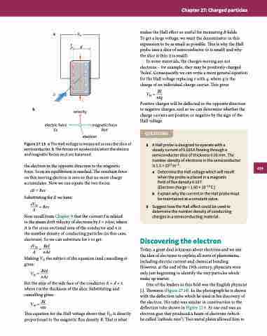
Figure 27.13 a The Hall voltage is measured across the slice of semiconductor. b The forces on an electron when the electric and magnetic forces on it are balanced.
the electron in the opposite direction to the magnetic force. Soon an equilibrium is reached. The resultant force on this moving electron is zero so that no more charge accumulates. Now we can equate the two forces:
eE = Bev
Substituting for E we have:
eVH =Bev d
Now recall from Chapter 9 that the current I is related to the mean drift velocity of electrons by I = nAve, where A is the cross-sectional area of the conductor and n is the number density of conducting particles (in this case, electrons). So we can substitute for v to get:
eVH = BeI d nAe
Making VH the subject of the equation (and cancelling e) gives:
VH = BId nAe
But the area of the side face of the conductor A = d × t, where t is the thickness of the slice. Substituting and cancelling gives:
VH = BI nte
This equation for the Hall voltage shows that VH is directly proportional to the magnetic flux density B. That is what
electron
429
