
Page 446 - Physics Coursebook 2015 (A level)
P. 446
Cambridge International A Level Physics
10
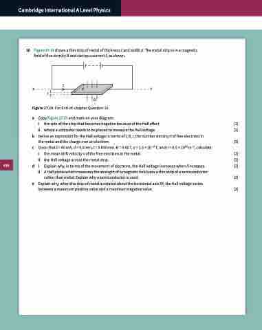
Figure 27.19 shows a thin strip of metal of thickness t and width d. The metal strip is in a magnetic field of flux density B and carries a current I, as shown.
XIdY t
B
Figure 27.19 For End-of-chapter Question 10.
a Copy Figure 27.19 and mark on your diagram:
i the side of the strip that becomes negative because of the Hall effect [1]
ii where a voltmeter needs to be placed to measure the Hall voltage. [1]
b Derive an expression for the Hall voltage in terms of I, B, t, the number density n of free electrons in
the metal and the charge e on an electron. [3]
c GiventhatI=40mA,d=9.0mm,t=0.030mm,B=0.60T,e=1.6×10⁻¹⁹Candn=8.5×1028m–3,calculate:
i the mean drift velocity v of the free electrons in the metal [2]
ii the Hall voltage across the metal strip. [2]
d i
ii A Hall probe which measures the strength of a magnetic field uses a thin strip of a semiconductor
Explain why, in terms of the movement of electrons, the Hall voltage increases when I increases. [2]
rather than metal. Explain why a semiconductor is used. [2] e Explain why, when the strip of metal is rotated about the horizontal axis XY, the Hall voltage varies
between a maximum positive value and a maximum negative value. [2]
434
