
Page 451 - Physics Coursebook 2015 (A level)
P. 451
Chapter 28: Electromagnetic induction
Induced e.m.f.
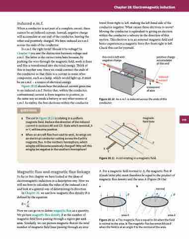
When a conductor is not part of a complete circuit, there cannot be an induced current. Instead, negative charge will accumulate at one end of the conductor, leaving the other end positively charged. We have induced an e.m.f. across the ends of the conductor.
Is e.m.f. the right term? Should it be voltage? In Chapter 9 you saw the distinction between voltage and e.m.f. The latter is the correct term here because, by pushing the wire through the magnetic field, work is done and this is transformed into electrical energy. Think of this in another way. Since we could connect the ends of the conductor so that there is a current in some other component, such as a lamp, which would light up, it must be an e.m.f. – a source of electrical energy.
Figure 28.10 shows how the induced current gives rise to an induced e.m.f. Notice that, within the conductor, conventional current is from negative to positive, in
the same way as inside a battery or any other source of e.m.f. In reality, the free electrons within the conductor
QUESTIONS
2 The coil in Figure 28.11 is rotating in a uniform magnetic field. Deduce the direction of the induced current in sections AB and CD. State which terminal, X or Y, will become positive.
3 When an aircraft flies from east to west, its wings are an electrical conductor cutting across the Earth’s magnetic flux. In the northern hemisphere, which wingtip will become positively charged? Why will this wingtip be negative in the southern hemisphere?
Magnetic flux and magnetic flux linkage
So far in this chapter we have looked at the ideas of electromagnetic induction in a descriptive way. Now we will see how to calculate the value of the induced e.m.f. and look at a general way of determining its direction.
In Chapter 26, we saw how magnetic flux density B is defined by the equation
B=F IL
Now we can go on to define magnetic flux as a quantity. We picture magnetic flux density B as the number of magnetic field lines passing through a region per unit area. Similarly, we can picture magnetic flux as the total number of magnetic field lines passing through an area
travel from right to left, making the left-hand side of the conductor negative. What causes these electrons to move? Moving the conductor is equivalent to giving an electron within the conductor a velocity in the direction of this motion. This electron is in an external magnetic field and hence experiences a magnetic force Bev from right to left. Check this out for yourself.
this end is left with negative charge
−
positive charge accumulates at this end
+ induced current
movement of wire
Figure 28.10 An e.m.f. is induced across the ends of the conductor.
B
C
A XYD
magnetic field lines
Figure 28.11 A coil rotating in a magnetic field.
A. For a magnetic field normal to A, the magnetic flux Φ (Greek letter phi) must therefore be equal to the product of magnetic flux density and the area A (Figure 28.12a).
a b
normal
B
BθB
area A
area A
Figure 28.12 a The magnetic flux is equal to BA when the field is normal to the area. b The magnetic flux becomes BA cos θ when the field is at an angle θ to the normal of the area.
439
S
