
Page 455 - Physics Coursebook 2015 (A level)
P. 455
Chapter 28: Electromagnetic induction
Lenz’s law
We use Faraday’s law to calculate the magnitude of an induced e.m.f. Now we can go on to think about the direction of the e.m.f. – in other words, which end of a wire or coil moving in a magnetic field becomes positive, and which becomes negative.
Fleming’s right-hand rule gives the direction of an induced current. This is a particular case of a more general law, Lenz’s law, which will be explained in this section. First, we will see how the motor effect and the generator effect are related to each other.
The origin of electromagnetic induction
So far, we have not given an explanation of electromagnetic induction. You have seen, from the experiments at the beginning of this chapter, that it does occur, and you know the factors that affect it. But what is the origin of the induced current?
Figure 28.20 gives an explanation. A straight wire XY is being pushed downwards through a horizontal magnetic field of flux density B. Now, think about the free electrons in the wire. They are moving downwards, so they are in effect an electric current. Of course, because electrons are negatively charged, the conventional current is flowing upwards.
We now have a current flowing across a magnetic
field, and the motor effect will therefore come into play. Each electron experiences a force of magnitude Bev.
Using Fleming’s left-hand rule, we can find the direction of the force on the electrons. The diagram shows that the electrons will be pushed in the direction from X to Y. So a current has been induced to flow in the wire; the direction of the conventional current is from Y to X.
Now we can check that Fleming’s right-hand rule gives the correct directions for motion, field and current, which indeed it does.
So, to summarise, there is an induced current
because the electrons are pushed by the motor effect. Electromagnetic induction is simply a consequence of the motor effect.
In Figure 28.20, electrons are found to accumulate at Y. This end of the wire is thus the negative end of the e.m.f. and X is positive. If the wire was connected to an external circuit, electrons would flow out of Y, round the circuit, and back into X. Figure 28.21 shows how the moving wire is equivalent to a cell (or any other source of e.m.f.).
induced current
movement of wire
magnetic field lines
current through cell
++
conductor
pushed downwards
induced Y current
movement of electrons
magnetic field lines
Figure 28.20 Showing the direction of the induced current.
a Incorrect
south
b Correct
north
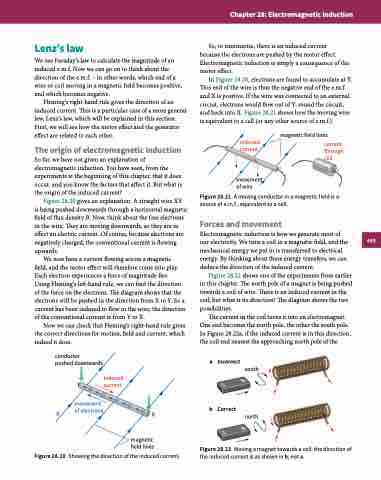
Figure 28.22 Moving a magnet towards a coil: the direction of the induced current is as shown in b, not a.
Figure 28.21
A moving conductor in a magnetic field is a source of e.m.f., equivalent to a cell.
Forces and movement
Electromagnetic induction is how we generate most of our electricity. We turn a coil in a magnetic field, and the mechanical energy we put in is transferred to electrical energy. By thinking about these energy transfers, we can deduce the direction of the induced current.
Figure 28.22 shows one of the experiments from earlier in this chapter. The north pole of a magnet is being pushed towards a coil of wire. There is an induced current in the coil, but what is its direction? The diagram shows the two possibilities.
The current in the coil turns it into an electromagnet. One end becomes the north pole, the other the south pole. In Figure 28.22a, if the induced current is in this direction, the coil end nearest the approaching north pole of the
B
X
443
S
N
S
N
