
Page 458 - Physics Coursebook 2015 (A level)
P. 458
Cambridge International A Level Physics
446
the kinetic energy of the train can be used to turn the electric motor to generate an induced e.m.f. With the appropriate electronics the energy from the induced current can be passed back to the power supply that runs the train. This is an example of regenerative braking.
Generators
We can generate electricity by spinning a coil in a magnetic field. This is equivalent to using an electric motor backwards. Figure 28.26 shows such a coil in
three different orientations as it spins. Notice that the
rate of change of flux linkage is maximum when the coil
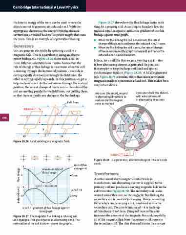
is moving through the horizontal position – one side is cutting rapidly downwards through the field lines, the other is cutting rapidly upwards. In this position, we get a large induced e.m.f. As the coil moves through the vertical position, the rate of change of flux is zero – the sides of the coil are moving parallel to the field lines, not cutting them, so that there is hardly any change in the flux linkage.
Figure 28.27 shows how the flux linkage varies with time for a rotating coil. According to Faraday’s law, the induced e.m.f. is equal to minus the gradient of the flux linkage against time graph.
■■ When the flux linking the coil is maximum, the rate of change of flux is zero and hence the induced e.m.f. is zero.
■■ When the flux linking the coil is zero, the rate of change of flux is maximum (the graph is steepest) and hence the induced e.m.f. is also maximum.
Hence, for a coil like this we get a varying e.m.f. – this
is how alternating current is generated. In practice,
it is simpler to keep the large coil fixed and spin an electromagnet inside it (Figure 28.28). A bicycle generator (see Figure 28.7) is similar, but in this case a permanent magnet is made to spin inside a fixed coil. This makes for a very robust device.
field lines
iron core (the rotor), wound in alternating directions to produce electromagnet poles as marked
iron outer shell (the stator), with wire coil wound
in alternating directions
rotation
X
XY Y YX
Figure 28.26 A coil rotating in a magnetic field.
0
0
maximum rate of
flux change Time
e.m.f. = maximum
e.m.f. = –gradient of flux linkage against time graph
Figure 28.27 The magnetic flux linking a rotating coil as it changes. This gives rise to an alternating e.m.f. The orientation of the coil is shown above the graphs.
rate of flux change = 0
Figure 28.28 In a generator, an electromagnet rotates inside a coil.
Transformers
Another use of electromagnetic induction is in transformers. An alternating current is supplied to the primary coil and produces a varying magnetic field in the soft iron core (Figure 28.30). The secondary coil is also wound round this core, so the magnetic flux linking the secondary coil is constantly changing. Hence, according to Faraday’s law, a varying e.m.f. is induced across the secondary coil. The core is laminated – it is made up
of thin sheets of soft iron. Using soft iron in the core increases the amount of the magnetic flux and, hopefully, all of the magnetic flux from the primary coil passes to the secondary coil. The thin sheets of iron in the core are
e.m.f. = 0
Time
output
S
N
N
S
S
N
Induced e.m.f. Flux linkage
