Page 814 - Introduction to Programming with Java: A Problem Solving Approach
P. 814
                780 Appendix 7 UML Diagrams
   : Mouse2Driver
create mouse
input days
classes
: Mouse2
mickey : Mouse2
set growth rate
grow (days)
       object
          control flow
    print mickey's attributes
    data flow
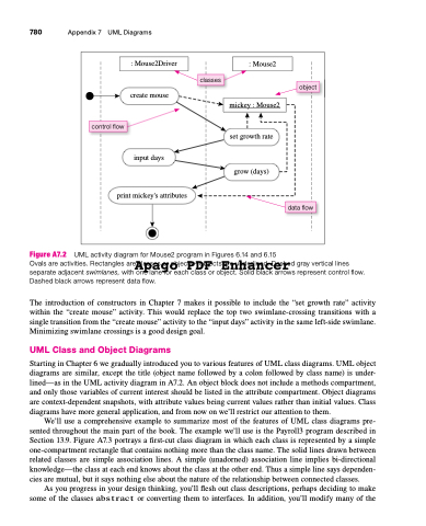
 Figure A7.2 UML activity diagram for Mouse2 program in Figures 6.14 and 6.15
Ovals are activities. Rectangles are classes or objects—objects are underlined. Dashed gray vertical lines
Apago PDF Enhancer
separate adjacent swimlanes, with one lane for each class or object. Solid black arrows represent control flow. Dashed black arrows represent data flow.
The introduction of constructors in Chapter 7 makes it possible to include the “set growth rate” activity within the “create mouse” activity. This would replace the top two swimlane-crossing transitions with a single transition from the “create mouse” activity to the “input days” activity in the same left-side swimlane. Minimizing swimlane crossings is a good design goal.
UML Class and Object Diagrams
Starting in Chapter 6 we gradually introduced you to various features of UML class diagrams. UML object diagrams are similar, except the title (object name followed by a colon followed by class name) is under- lined—as in the UML activity diagram in A7.2. An object block does not include a methods compartment, and only those variables of current interest should be listed in the attribute compartment. Object diagrams are context-dependent snapshots, with attribute values being current values rather than initial values. Class diagrams have more general application, and from now on we’ll restrict our attention to them.
We’ll use a comprehensive example to summarize most of the features of UML class diagrams pre- sented throughout the main part of the book. The example we’ll use is the Payroll3 program described in Section 13.9. Figure A7.3 portrays a first-cut class diagram in which each class is represented by a simple one-compartment rectangle that contains nothing more than the class name. The solid lines drawn between related classes are simple association lines. A simple (unadorned) association line implies bi-directional knowledge—the class at each end knows about the class at the other end. Thus a simple line says dependen- cies are mutual, but it says nothing else about the nature of the relationship between connected classes.
As you progress in your design thinking, you’ll flesh out class descriptions, perhaps deciding to make some of the classes abstract or converting them to interfaces. In addition, you’ll modify many of the


