
Page 113 - M1-12 Ops Manual McMurdo 2016
P. 113
4.2 - Step 2: Wiring
Careful attention must be paid when attaching the wiring to the MaxPac to ensure proper and safe opera- tion. This section contains detailed information on how to connect the power, resistive load, ground, and command signal wiring.
WARNING
Hazardous Voltage: Only quali ed personnel should perform electrical wiring for the MaxPac Power Paks. LETHALLY HIGH VOLTAGES are associated with this equipment and are danger- ous if improperly installed.
IMPORTANT: Select installation wiring that is in accordance with the National Electrical Code and any local standards that may be applicable.
4.2.1 - Touch-Safe Design
If the MaxPac model you purchased is of a Touch-Safe design, follow the steps on the following page to install the electrical wiring. This will ensure the wiring is done properly while maintaining the Touch-Safe feature. If your MaxPac is of an Open design below 400 Amps, disregard this subsection.
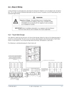
The following is a detailed drawing of a Touch-Safe unit:
TOUCH-SAFE COVER PROVIDES WIRE ENTRANCE AND EXIT THROUGH SEALS COVERING THE WIRE WINDOW. REMOVAL OF THE TAPE BEHIND THE WINDOWS TO BE USED ALLOWS WIRES TO PASS. THE TAPE REMAINS ON UNUSED WINDOWS TO PROVIDE TOUCH SAFE FEATURE.
LONG LIFE, HIGH OUTPUT BALL BEARING FANS PROVIDE RELIABLE COOLING
1-888-996-9258
© 2014 Chromalox®, Inc.
- 11 -
BUS BAR DESIGN ALLOWS FOR WIRING FROM EITHER DIRECTION AND MULTIPLE LOAD CIRCUITS
COOLING AIR
COOLING AIR
COVER PROVIDES FOR TOUCH SAFE FEATURE
BUS BAR DESIGN ALLOWS FOR WIRING FROM EITHER DIRECTION AND MULTIPLE LOAD CIRCUITS
SCR HEATSINK FINS
FUSE
