
Page 117 - M1-12 Ops Manual McMurdo 2016
P. 117
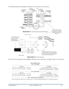
The following drawings show proper installation of the crimp lugs on the bus bars:
Illustration 1: View From Rear Ventilated Panel LOAD BUS BAR
All bolts must mount with excess bolt lengths toward the fuse to main- tain required electrical clearances.
1/0 through 500 mcm wire must mount on the fuse side of the bus
bar as shown to maintain required electrical clearances
LINE BUS BAR
Smaller wire, #1 through #8, often used for power distribution, can be connected to both sides of the load bus. Wiring must be bent slightly to align with the windows in the top of the touch safe units.
Illustration 2: View From Top
The bus bars are designed to accept NEMA standard two-hole crimp lugs in accordance with the charts below.
Touch-Safe Units
Input Bus Upto(3)1/0-300mcm(70mm2 —150mm2)
Upto(2)350-500mcm(185mm2 —240mm2)
Input Bus Upto(4)1/0-300mcm(70mm2 —150mm2)
Upto(3)350-500mcm(185mm2 —240mm2)
100 - 400 Amps
550 - 650 Amps
Output Bus Upto(10)#8-#1(10mm2 —50mm2) Upto(3)1/0-300mcm(70mm2 —150mm2) Upto(2)350-500mcm(185mm2 —240mm2)
Output Bus Upto(12)#8-#1(10mm2 —50mm2) Upto(4)1/0-300mcm(70mm2 —150mm2) Upto(3)350-500mcm(185mm2 —240mm2)
800 - 1200 Amps Open Design
Input and output bus drilled to accomodate qty (4) 1/0 - 500 mcm NEMA standard two-hole crimp lugs per phase.
1-888-996-9258 © 2014 Chromalox®, Inc. - 15 -
FUSE
FAN END
SCR
