
Page 120 - M1-12 Ops Manual McMurdo 2016
P. 120
- 18 -
© 2014 Chromalox®, Inc.
1-888-996-9258
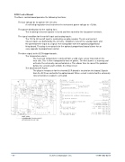
SCR Control Board
The Basic control board provides the following functions:
The low voltage dc to operate the circuitry:
A switching regulator circuit converts the instrument power voltage to +12Vdc.
The power distribution for the cooling fans:
The incoming instrument power is fused and then routed to the fan power terminals.
The signal condition for the on/off input and analog inputs:
The 120 to 240 on/off input is isolated by an opto-coupler. The dc and contact closure inputs are buffered by the circuitry. Ampli ers convert the analog inputs and the potentiometer input to a signal level compatible with the optional proportional ring board. The plug-in receptacle for the optional proportional board allows for an easy upgrade to proportional control.
The drive signal to the SCR trigger boards: The temperature alarm:
The heat sink temperature is derived from a solid state sensor mounted on the heat sink. This is then compared to two set points. The rst alarm is a warning and activates the externally connected device. This allows time to correct the problem before the second alarm inhibits the ring circuit.
The Shorted SCR Alarm:
The plug-in receptacle for the shorted SCR board is located on this board. Signals from the SCR are routed to the option board. When a short is detected the externally connected device output is activated.
2AMP (2AG)
CHROMALOX P/N 0024-01097 LITTLEFUSE P/N 225 002
(@)
() () ()
