
Page 15 - Demo
P. 15
–
1
S
10 4
2
7 8
(Fig. 14) for 175v2 to 750v2 cm2 actuator areas (not for 240 cm2)
– Versions for other control media (e.g. water) available on request
Thesignalpressurep createstheforceF=p ·Aatthedia- st st
phragm surface A which is opposed by the springs (10) in the actuator. The bench range is determined by the number of springs used and their compression, taking into account the rated travel. The travel H is proportional to the signal pressure pst. The direction of action of the actuator stem (7) depends on how the springs are installed in the actuator and the location of the signal pressure connection (S).
Actuators with 175v2, 350v2, 355v2 and 750v2 cm2 actua- tor areas are designed with a full rolling diaphragm (see Fig. 10). The diaphragm of actuators with 240, 350 and 700 cm2 actuator areas is clamped-in (see Fig. 9).
The stem connector (26) connects the actuator stem (7) with the plug stem of the valve.
The adjustable (Fig. 13) is suitable for actuators with actuator areas of 120, 175v2, 240, 350v2, 355, 700 or 750v2 cm2. Using the travel stop, the actuator travel can be limited by up to 50 % in both directions (actua- tor stem extends or retracts) and permanently adjusted.
Actuators are available with the following directions of action:
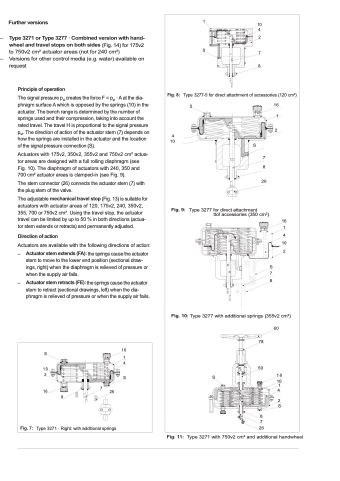
Type 3277-5 for direct attachment of accessories (120 cm2)
16 1
2
7 8
26
S
4 10
S
Type 3277 for direct attachment
ttof accessories (350 cm2)
–
–
S 7 8
the springs cause the actuator stem to move to the lower end position (sectional draw-
ings, right) when the diaphragm is relieved of pressure or when the supply air fails.
the springs cause the actuator stem to retract (sectional drawings, left) when the dia-
phragm is relieved of pressure or when the supply air fails.
16 1 4 10 2
Type 3277 with additional springs (355v2 cm2) 60
S
10 2
16
16
1 4
78
50
8 7
SS
16
10 1 4
2 S
7
26
8
Type 3271 · Right: with additional springs 26
Type 3271 with 750v2 cm2 and additional handwheel
