
Page 27 - 2020-2021 Catalogue
P. 27
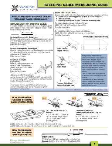
STEERING CABLE MEASURING GUIDE
HOW TO MEASURE STEERING CABLES “MEASURE TWICE. ORDER ONCE.”
REPLACEMENT OF EXISTING CABLE:
If possible, find the part number stamped on the plastic jacket of the old cable. If you removed the old cable, measure for the replacement cable as follows:
"Y" IN INCHES
For Rotary Steering Cable Replacement,
Measure Existing Cable as follows: Measure plastic cable jacket (“Y” dimension, shown in above drawing) in inches, add 18", and round up to the next foot. Order that length cable.
For Rack Steering Cable Replacement,
Measure Existing Cable as follows: Measure plastic cable jacket (“Y” dimension shown in above drawing) in inches, add 30", and round up to the next foot. Order that length cable.
For JBS Jet Boat Cable Replacement, Measure Existing Cable as follows: Measure cable from tip to tip. (Round up to next foot if needed for whole foot.) Order that length cable.
JBS helms are ONLY for smaller jets such as Mercury Sport Jet®, OMC Turbo Jet®, etc. and look like the helm depicted at right. If your jet steering is different, contact SeaStar Solutions Technical Service.
If your engine does not have a tilt tube cable connection, see “Connection Kits” pages later in this section to get the information or visit us on-line.
NEW INSTALLATION:
Measure cable routing path from wheel center line to engine connection, as follows:
A = Center line of wheel to gunwale (or deck, if routed downward), B = Dash to transom, C = Gunwale to centerline of cable connection at centered tiller.
For Cable Installations through the Engine Tilt Tube: Add A, B & C + 6", and round up to the next foot. Order that length cable.
For Cables Mounted to Transom, Splashwell or Stringer: Add A, B & C, then subtract 6" and round up to the next foot. Order that length cable.
For more information see: www.seastarsolutions.com
HOW TO MEASURE FOR NEW STEERING CABLE INSTALLATION
Fig. 1
Fig. 2
Fig. 3
TRANSOM SUPPORT or SPLASHWELL MOUNTING - Fig. 2-3 Example: A(2.5')+B(10.5')+C(3’)=16' 16' - 8" (two 90˚ bends) = 15'4" Round up to 16"
®
TILT TUBE MOUNTING - Fig. 1 Example: A(2.5')+B(10.5')+C(3’)=16' 16' - 8" (two 90˚ bends) = 15'4" 15'4" + 12" (tilt tube) = 16'4" Round up to 17"
Add the lengths of A + B + C together and subtract 4" (10 cm) for each 90˚ bend. Add 12" (30.5 cm) for the engine tilt tube. To order in foot length, round up to the nearest whole foot.
HOW TO MEASURE FOR REPLACEMENT STEERING CABLES
For more information see: www.uflexusa.com
D = Conduit length
ORDER LENGTH:
Cable Through Engine Tilt Tube
Splashwell Cable Mount
Transom Cable Mount (similar to stringer type)
C
TYPICAL SINGLE STATION ROUTING
A
B
A single-cable, starboard drive push-pull mechanical cable system is shown in this diagram. If your mechanical system is different than the one depicted and/or you have any questions about mechanical steering after reviewing this guide, please contact SeaStar Solutions Technical Service. Cable routings (such as those found on pontoon boats) may vary from this drawing. Confirm length by laying a garden hose (or similar object) along cable path and measure run from wheel to engine connection point.
"D" Dimension + 22" and round up to the next whole foot. Example: D=120" + 22" = 142" (11'8"). Round up to 12 ft.
1
