
Page 41 - 2020-2021 Catalogue
P. 41
MECHANICAL STEERING CONNECTION KITS
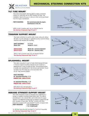
TILT TUBE MOUNT
This is the most popular steering cable-to-engine connection method for outboards with an ABYC standard tilt tube. This installation requires the use of a link arm which can be purchased from the engine manufacturer.
PARTS REQUIRED: We recommend using the engine manufacturer's link arm.
NOTE: In salt or brackish water only use Stainless Steel kit
See Steering Components Page 16 and 17
TRANSOM SUPPORT MOUNT
This Cable connection is used for older model outboards without tilt tubes, low HP outboards or applications where transom design interferes with standard tilt mounting. G
Link Arm
(From engine manufacturer)
PARTS REQUIRED: Master Kits:
069-27256 069-27255
D, G & H Include D, G & H
Master Kit - Corrosion Resistant Master Kit - Stainless Steel
D
NOTE: In salt or brackish water only use Stainless Steel kit
See Steering Components Page 16 and 17
SPLASHWELL MOUNT
This cable connection is used on boats where standard tilt tube or transom support mounting methods are pre-cluded by a splashwell box or lack of engine tilt tube. The mounting surface is usually near perpendicular to the transom and between 12 and 16 inches from the centre line of the boat and/or tiller
(25-33" Total Slashwell Width).
PARTS REQUIRED: 90° Splashwell Mounting - B, H ORDER NO. 069-27254
15° Splashwell Mounting - A, H
ORDER NO. 069-27253
NOTE: Not for thru hull applications.
See Steering Components Page 16 and 17
INBOARD STRINGER SUPPORT MOUNT
This cable connection is used on inboards and is attached to a stringer or suitable mounting bracket below deck. The cable is perpendicular to the centered tiller and in half stroke for proper operation. An additional bracket may be needed to support the ball post. Available in heavy duty “Ski Boat” versions with either
long (4.5") or short (2.25") post standoff to centre of support tube.
PARTS REQUIRED: E, G, H (long post) or F, G, H (short post)
For Ski Boat Clamp Block Kit, purchase E or F and G & H separately.
See Steering Components Page 16 and 17
H
H
For more information see: www.seastarsolutions.com
15
®
A or B (A shown)
G
E or F (E shown)
H
