
Page 124 - McWane Poles Sales Manual 2024
P. 124
124
McWane Poles, A Division of McWane Inc.
TESTING DOCUMENTS
Date of Report:
Manufacturer:
Subject:
Location:
Date:
Pole Description:
September 18, 2017
McWane Ductile Iron Pole
Full-Scale, Horizontal Bending Test
McWane Plant - Coshocton, Ohio
September 6th, 2017
80 / H4
Test Setup: See included drawing for pole test layout (Figure 1)
Test Result: See included graph (Figure 2)
Pole Design: See included PLS Pole design output
Load Cycle
Load
Measured
(kips)
Load
Adjusted
(kips)
Deflection
Measured
(inches)
Deflection
Adjusted
(inches)
1 0 0 0 0
1 0.64 0.63 5 4.5
1 0.96 0.95 9 8.9
1 1.42 1.41 18 17.8
1 2.00 1.98 24 23.8
1 2.48 2.46 29 28.7
1 3.04 3.01 38 37.6
1 3.96 3.92 51 50.5
1 4.48 4.44 59 58.4
1 4.96 4.91 67 66.3
1 5.48 5.43 76 75.2
1 5.68 5.62 85 84.2
1 0 0 11 10.9
2 0.48 0.48 22 21.8
2 0.96 0.95 28 27.7
2 1.48 1.47 35 34.7
2 2.00 1.98 40 39.6
2 2.48 2.46 48 47.5
2 2.96 2.93 54 53.5
2 3.48 3.45 60 59.4
2 4.04 4.00 66 65.3
2 4.52 4.47 73 72.3
2 4.96 4.91 78 77.2
2 5.52 5.46 86 85.1
2 6.08 6.02 97 96.0
2 6.48 6.42 112 110.9
2 6.68 6.61 138 136.6
2 6.80 (failure at
ground line) 6.73 156 154.4
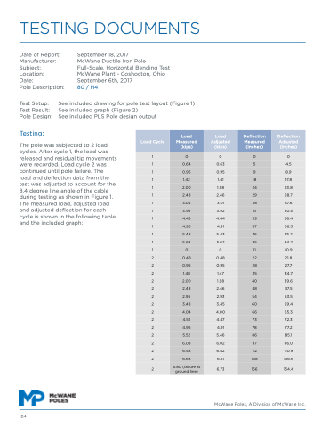
Testing:
The pole was subjected to 2 load
cycles. After cycle 1, the load was
released and residual tip movements
were recorded. Load cycle 2 was
continued until pole failure. The
load and deflection data from the
test was adjusted to account for the
8.4 degree line angle of the cable
during testing as shown in Figure 1.
The measured load, adjusted load
and adjusted deflection for each
cycle is shown in the following table
and the included graph:
