
Page 211 - Green - Maritime Archaeology: A Technical Handbook. 2nd ed
P. 211
190 Maritime Archaeology: A Technical Handbook, Second Edition
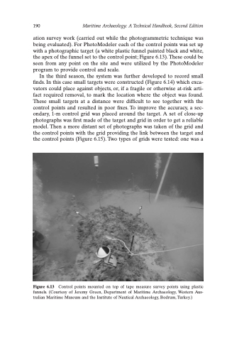
ation survey work (carried out while the photogrammetric technique was being evaluated). For PhotoModeler each of the control points was set up with a photographic target (a white plastic funnel painted black and white, the apex of the funnel set to the control point; Figure 6.13). These could be seen from any point on the site and were utilized by the PhotoModeler program to provide control and scale.
In the third season, the system was further developed to record small finds. In this case small targets were constructed (Figure 6.14) which exca- vators could place against objects, or, if a fragile or otherwise at-risk arti- fact required removal, to mark the location where the object was found. These small targets at a distance were difficult to see together with the control points and resulted in poor fixes. To improve the accuracy, a sec- ondary, 1-m control grid was placed around the target. A set of close-up photographs was first made of the target and grid in order to get a reliable model. Then a more distant set of photographs was taken of the grid and the control points with the grid providing the link between the target and the control points (Figure 6.15). Two types of grids were tested: one was a
Figure 6.13 Control points mounted on top of tape measure survey points using plastic funnels. (Courtesy of Jeremy Green, Department of Maritime Archaeology, Western Aus- tralian Maritime Museum and the Institute of Nautical Archaeology, Bodrum, Turkey.)
