
Page 19 - ConcreCem - State of the Art
P. 19
7 ConcreCem against chloride induced Corrosion of reinforcement
Most concrete structures show good performance over a long period of time, partly as a result of the passive environment provided by the concrete to the reinforcing steel. However, changes to the concrete environment itself (for example using salt water or salt aggregate) can make it possible to change the corrosiveness leading to the initiation of corrosion beneath apparently solid concrete.
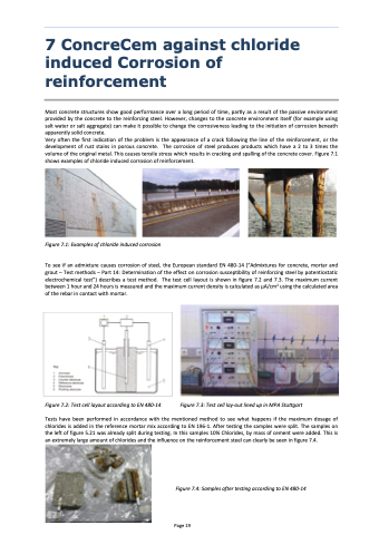
Very often the first indication of the problem is the appearance of a crack following the line of the reinforcement, or the development of rust stains in porous concrete. The corrosion of steel produces products which have a 2 to 3 times the volume of the original metal. This causes tensile stress which results in cracking and spalling of the concrete cover. Figure 7.1 shows examples of chloride induced corrosion of reinforcement.
Figure 7.1: Examples of chloride induced corrosion
To see if an admixture causes corrosion of steel, the European standard EN 480-14 (“Admixtures for concrete, mortar and grout – Test methods – Part 14: Determination of the effect on corrosion susceptibility of reinforcing steel by potentiostatic electrochemical test”) describes a test method. The test cell layout is shown in figure 7.2 and 7.3. The maximum current between 1 hour and 24 hours is measured and the maximum current density is calculated as μA/cm2 using the calculated area of the rebar in contact with mortar.
Figure 7.2: Test cell layout according to EN 480-14 Figure 7.3: Test cell lay-out lined up in MPA Stuttgart
Tests have been performed in accordance with the mentioned method to see what happens if the maximum dosage of chlorides is added in the reference mortar mix according to EN 196-1. After testing the samples were split. The samples on the left of figure 5.21 was already split during testing. In this samples 10% Chlorides, by mass of cement were added. This is an extremely large amount of chlorides and the influence on the reinforcement steel can clearly be seen in figure 7.4.
Figure 7.4: Samples after testing according to EN 480-14
Page 19
