
Page 30 - Climate Control News Magazine July 2021
P. 30
Troubleshooting
Design tips to improve chiller efficiency
MECHANICAL ENGINEER AND NABERS ACCREDITED ASSESSOR, AHMAD FRAIJ, PRESENTS A RANGE OF OPTIONS TO IMPROVE CHILLER SYSTEM EFFICIENCY DURING THE DESIGN STAGE.
TO SELECT THE best system, a holistic ap- proach is key to make budget and achieve opti- mal efficiency. When it comes to efficiency my personal preference is a variable speed chiller with magnetic bearing compressors. Air cooled chillers should have EC fans for the condenser and should be equipped with an adiabatic sys- tem to achieve even greater efficiencies.
Generally, chiller efficiency depends on the compressor lift, which is the difference between the suction and discharge pressures.
The smaller the difference in pressures the higher the efficiency of the chiller. The pressure is proportional to the temperature and therefore, the compressor lift.
”REDUCING WATER FLOW RATES MEANS SMALLER PIPES, WHICH LOWERS CAPITAL COSTS.”
Chiller efficiency depends on the leaving chilled water temperature and the leaving con- denser water temperatures for the water cooled chillers or the leaving air temperature for the air cooled chillers.
Based on this, we can see that increasing the leaving chilled water temperature from the chill- er will improve its efficiency. As a rule of thumb, for every 1°C increase in leaving chilled water temperature, there is a three per cent reduction in chiller energy consumption. Therefore, always design your system with high leaving chilled wa- ter temperature. Note that increasing the chilled
water temperature leads to bigger coils in the AHU’s and FCU’s so it is important for the de- signer to carry out a life cycle cost analysis to se- lect the best system.
The designer should also consider selecting chilled beams or displacement diffusers for the chilled water system because these types of sys- tems require higher chilled water supply temper- ature that can reach 16°C. This high chilled wa- ter temperature allows you to select smaller chillers while also improving chiller efficiency.
FLOW RATE
Most engineers design the chiller system at 5°C delta T on both the chilled water side and also on the condenser side if the chiller is water cooled. This is the old way to design a system but due to the need for energy efficiency, we need to increase delta T to 8 – 10°C to reduce the flow rate so we can select smaller pumps to reduce energy use.
Further, reducing the condenser water flow rate for the water cooled chillers, will lead to a smaller cooling tower and smaller tower fan, which also reduces energy consumption. Don’t forget reducing water flow rates means smaller pipes, reducing the capital cost of the project.
CONNECTION CONFIGURATION
With most projects the connection is parallel for water cooled chillers but there is a more efficient option, especially for the large capacity chillers.
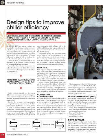
Series counter-flow chillers configuration (as shown in the figure below) reduces the chillers lift and improves their efficiency. You can see from the figure below that the chiller that has lower leaving chiller water temperature has also the lower leaving condenser water temperature and vice versa.
This configuration makes both chillers see ap- proximately the same smaller lift (26°C) rather than seeing the bigger lift (31°C) if they are both connected in parallel. Chiller manufacturers claim that this configuration can improve chiller efficiency by up to 13 per cent.
VARIABLE SPEED DRIVES (VSDS)
Motor energy consumption is proportional to the cube of the flow rate so reducing the water or air flow rate will reduce the energy consumption of pumps and fans drastically. This should be specified with VSD’s including:
• Chilled Water Pumps with emphasis on varia- ble primary flow configuration, which saves on the initial and running costs.
• Condenser Water Pumps • Cooling Tower Fans
• Air Handling Units Fans
CONTROL VALVES
Using a Pressure Independent Control Valve (PICV) for the air terminal units such as FCU’s and AHU’s is much better than using the traditional combination of the 2-way control valve and bal- ancing valve. The 2-way control valve can change the flow rate supplied to the terminal unit based
38°C 33°C
28°C
17°C
12°C 7°C
CLIMATECONTROLNEWS.COM.AU
Upstream Chiller
Downstream Chiller
30
