
Page 72 - PBL71 OI/AXM630-EN AZTEC 600 SS (WIRO)
P. 72
Aztec 600 ISE ammonia and fluoride
Single-stream ion-selective analyzers
13 Maintenance
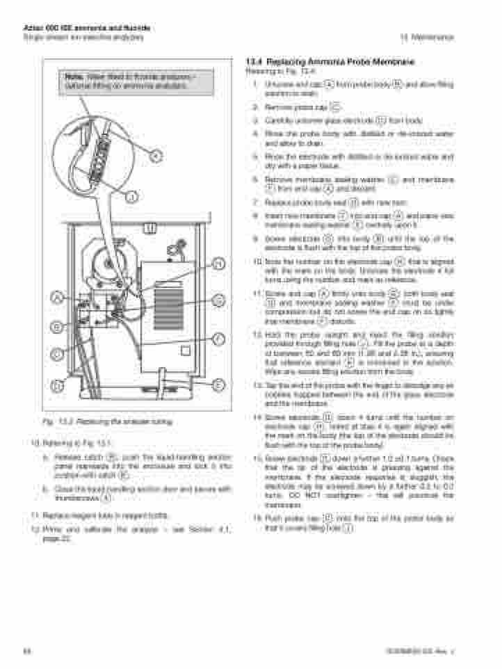
Note. Mixer fitted to fluoride analyzers – optional fitting on ammonia analyzers.
K
J
A
B C
D
H
G
F
E
68
OI/AXM630–EN Rev. J
Fig. 13.3 Replacing the analyzer tubing
10. Referring to Fig. 13.1:
a. Release catch B, push the liquid-handling section panel rearwards into the enclosure and lock it into position with catch B.
b. Close the liquid-handling section door and secure with thumbscrews A.
11. Replace reagent tube in reagent bottle.
12.Prime and calibrate the analyzer – see Section 4.1, page 22.
13.4 Replacing Ammonia Probe Membrane
Referring to Fig. 13.4:
1. Unscrew end cap A from probe body B and allow filling solution to drain.
2. Remove probe cap C.
3. Carefully unscrew glass electrode D from body.
4. Rinse the probe body with distilled or de-ionized water and allow to drain.
5. Rinse the electrode with distilled or de-ionized water and dry with a paper tissue.
6. Remove membrane sealing washer E and membrane F from end cap A and discard.
7. Replace probe body seal G with new item.
8. Insert new membrane F into end cap A and place new
membrane sealing washer E centrally upon it.
9. Screw electrode D into body B until the top of the
electrode is flush with the top of the probe body.
10. Note the number on the electrode cap H that is aligned with the mark on the body. Unscrew the electrode 4 full turns using the number and mark as reference.
11. Screw end cap A firmly onto body B; both body seal G and membrane sealing washer E must be under compression but do not screw the end cap on so tightly that membrane F distorts.
12.Hold the probe upright and inject the filling solution provided through filling hole J. Fill the probe to a depth of between 50 and 60 mm (1.96 and 2.36 in.), ensuring that reference element K is immersed in the solution. Wipe any excess filling solution from the body.
13. Tap the end of the probe with the finger to dislodge any air bubbles trapped between the end of the glass electrode and the membrane.
14.Screw electrode D down 4 turns until the number on electrode cap H, noted at step 4 is again aligned with the mark on the body (the top of the electrode should be flush with the top of the probe body).
15. Screw electrode D down a further 1.0 ±0.1 turns. Check that the tip of the electrode is pressing against the membrane. If the electrode response is sluggish, the electrode may be screwed down by a further 0.2 to 0.3 turns. DO NOT overtighten – this will puncture the membrane.
16. Push probe cap C onto the top of the probe body so that it covers filling hole J.
