
Page 135 - PBL614 IM/SM500F-EN SM500F ( WIRO)
P. 135
SM500F
Field mountable paperless recorder 7 Configuration
7.13.2 Math Block Configuration
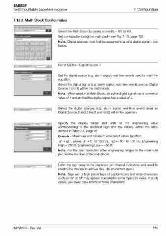
Select the Math Block to create or modify – M1 to M8.
Set the equation using the math pad – see Fig. 7.19, page 132.
Note. Digital sources must first be assigned to a valid digital signal – see below.
Reset Source / Digital Source 1
Set the digital source (e.g. alarm signal, real-time event) used to reset the equation.
Select the digital signal (e.g. alarm signal, real-time event) used as Digital Source 1 (md1) within the math block.
Note. When used in a Math Block, an active digital signal has a numerical value of 1 and an inactive digital signal has a value of 0.
Select the digital sources (e.g. alarm signal, real-time event) used as Digital Source 2 and 3 (md2 and md3) within the equation.
Specify the display range and units of the engineering value corresponding to the electrical high and low values, within the limits defined in Table 7.4, page 97.
Example – Maximum and minimum calculated values function:
a1+a2 , where a10 to 150 l/s, a2–50 to 100 l/s, Engineering
High = 250.0, Engineering Low = –50.0.
Note. For the best resolution enter engineering ranges to the maximum permissible number of decimal places.
Enter the tag name to be displayed on channel indicators and used to identify the channel in archive files. (16 characters max.).
Note. Tags with a high percentage of capital letters and wide characters such as 'W' or 'M' may appear truncated in some Operator views. In such cases, use lower case letters or fewer characters.
IM/SM500F Rev. AA
133
