
Page 149 - PBL614 IM/SM500F-EN SM500F ( WIRO)
P. 149
SM500F
Field mountable paperless recorder Appendix A – Signal Sources
Digital Input States
Source Name
Description
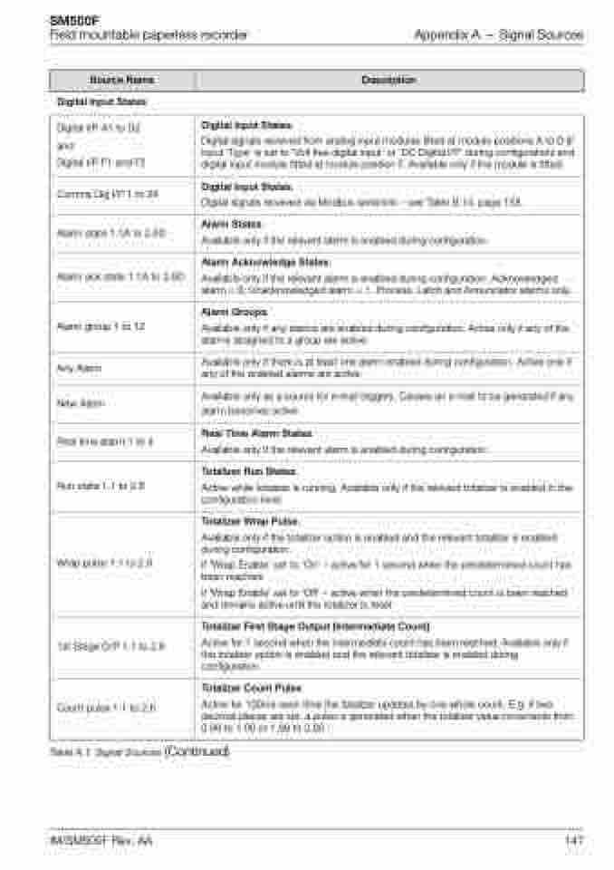
Digital I/P A1 to D2
and
Digital I/P F1 and F2
Digital Input States.
Digital signals received from analog input modules fitted at module positions A to D (if input 'Type' is set to 'Volt free digital input' or 'DC Digital I/P' during configuration) and digital input module fitted at module position F. Available only if the module is fitted.
Comms Dig I/P 1 to 24
Digital Input States.
Digital signals received via Modbus serial link – see Table B.14, page 158.
Alarm state 1.1A to 2.6D
Alarm States.
Available only if the relevant alarm is enabled during configuration.
Alarm ack state 1.1A to 2.6D
Alarm Acknowledge States.
Available only if the relevant alarm is enabled during configuration. Acknowledged alarm = 0; Unacknowledged alarm = 1. Process, Latch and Annunciator alarms only.
Alarm group 1 to 12
Alarm Groups.
Available only if any alarms are enabled during configuration. Active only if any of the alarms assigned to a group are active.
Any Alarm
Available only if there is at least one alarm enabled during configuration. Active only if any of the enabled alarms are active.
New Alarm
Available only as a source for e-mail triggers. Causes an e-mail to be generated if any alarm becomes active.
Real time alarm 1 to 4
Real Time Alarm States.
Available only if the relevant alarm is enabled during configuration.
Run state 1.1 to 2.6
Totalizer Run States.
Active while totalizer is running. Available only if the relevant totalizer is enabled in the configuration level.
Wrap pulse 1.1 to 2.6
Totalizer Wrap Pulse.
Available only if the totalizer option is enabled and the relevant totalizer is enabled
during configuration.
If 'Wrap Enable' set to 'On' – active for 1 second when the predetermined count has been reached.
If 'Wrap Enable' set to 'Off' – active when the predetermined count is been reached and remains active until the totalizer is reset
1st Stage O/P 1.1 to 2.6
Totalizer First Stage Output (Intermediate Count).
Active for 1 second when the intermediate count has been reached. Available only if the totalizer option is enabled and the relevant totalizer is enabled during configuration.
Count pulse 1.1 to 2.6
Totalizer Count Pulse.
Active for 100ms each time the totalizer updates by one whole count. E.g. if two decimal places are set, a pulse is generated when the totalizer value increments from 0.99 to 1.00 or 1.99 to 2.00
Table A.1 Signal Sources (Continued)
IM/SM500F Rev. AA 147
