
Page 160 - PBL614 IM/SM500F-EN SM500F ( WIRO)
P. 160
SM500F
Field mountable paperless recorder Appendix B – Modbus TCP/Modbus 485
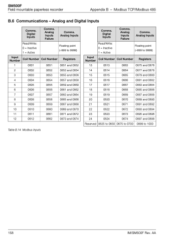
B.6 Communications – Analog and Digital Inputs
Input Number
1
2
3
4
5
6
7
8
9
10
11
12
Comms. Digital Inputs
Read/Write: 0 = Inactive 1 = Active
Coil Number
0601
0602
0603
0604
0605
0606
0607
0608
0609
0610
0611
0612
Comms. Analog Inputs Failure
Coil Number
0651
0652
0653
0654
0655
0656
0657
0658
0659
0660
0661
0662
Comms. Analog Inputs
Floating point (–999 to 9999)
Registers
0851 and 0852
0853 and 0854
0855 and 0856
0857 and 0858
0859 and 0860
0861 and 0862
0863 and 0864
0865 and 0866
0867 and 0868
0869 and 0870
0871 and 0872
0873 and 0874
Input Number
13
14
15
16
17
18
19
20
21
22
23
24
Reserved
Comms. Digital Inputs
Read/Write: 0 = Inactive 1 = Active
Coil Number
0613
0614
0615
0616
0617
0618
0619
0620
0621
0622
0623
0624
0625 to 0650
Comms. Analog Inputs Failure
Coil Number
0663
0664
0665
0666
0667
0668
0669
0670
0671
0672
0673
0674
0675 to 0700
Comms. Analog Inputs
Floating point (–999 to 9999)
Registers
0875 and 0876
0877 and 0878
0879 and 0880
0881 and 0882
0883 and 0884
0885 and 0886
0887 and 0888
0889 and 0890
0891 and 0892
0893 and 0894
0895 and 0896
0897 and 0898
0899 to 1000
Table B.14 Modbus Inputs
158 IM/SM500F Rev. AA
