
Page 179 - statbility for masters and mates
P. 179
KN Cross Curves of Stability
It has already been shown that the Stability Cross Curves for a ship are constructed by plotting the righting levers for an assumed height of the centre of gravity above the keel. In some cases the curves are constructed for an assumed KG of zero. The curves are then referred to as KN curves, KN being the righting lever measured from the keel. Figure 16.3(a) shows the KN curves for an imaginary ship called the M.V. `Cargo-Carrier'.
Stability and hydrostatic curves 167
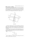
Fig. 16.3(b)
To obtain the righting levers for a particular displacement and KG the values of KN are ®rst obtained from the curves by inspection at the displacement concerned. The correct righting levers are then obtained by subtracting from the KN values a correction equal to the product of the KG and sin Heel.
In Figure 16.3(b), let KN represent the ordinate obtained from the curves. Also, let the ship's centre of gravity be at G so that KG represents the actual height of the centre of gravity above the keel and GZ represents the length of the righting lever.
Now
or
GZ XN
KN KX
GZ KN KG sin y
Thus, the righting lever is found by always subtracting from the KN ordinate a correction equal to KG sin heel.
