
Page 186 - statbility for masters and mates
P. 186
174 Ship Stability for Masters and Mates
Let us assume the true mean draft `dH' is 6 m. The Navel Architect or mate on board ship draws a horizontal line parallel to the SLWL at 6 m on the vertical axis right across all of the hydrostatic curves.
At each intersection with a curve and this 6m line, he projects downwards and reads off on the appropriate scale on the `x' axis.
For our hydrostatic curves, at a mean draft of 6 m, for example, we would obtain the following:
TPC 19:70 t MCTC 152:5 tm/cm
LCBe 0:80 m forward e KMT 7:46m
DisplaceMT 10 293 t
LCFe 0:05 m forward e KML 207:4 m
These values can then be used to calculate the new end drafts and transverse stability, if weights are added to the ship, discharged from the ship or simply moved longitudinally or transversely within the ship.
LCFe and LCBe are distances measured from amidships (e ). e
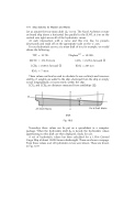
e Draft
Fig. 16.8
Nowadays these values can be put on a spreadsheet in a computer package. When the hydrostatic draft dH is keyed, the hydrostatic values appertaining to this draft are then displayed, ready for use.
A set of hydrostatic values has been calculated for a 135m General Cargo Ship of about 10 000 tonnes deadweight. These are shown overpage. From those values a set of hydrostatic curves were drawn. These are shown in Fig. 16.9.
