
Page 212 - ro membanes
P. 212
9.3 KEY FILTRATION SYSTEM COMPONENTS 195
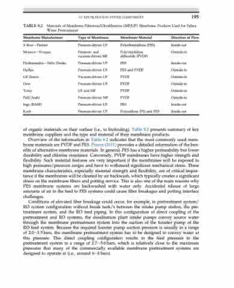
TABLE 9.2 Materials of Membrane Filtration/Ultrafiltration (MF/UF) Membrane Products Used for Saline Water Pretreatment
Membrane Manufacturer
X-flowdPentair MemcordEvoqua
HydranauticsdNitto Denko Hyflux
GE Zenon
Dow
Toray Pall/Asahi Inge (BASF) Koch
Type of Membrane
Pressure-driven UF
Pressure- and vacuum-driven MF
Pressure-driven UF Pressure-driven UF Vacuum-driven UF Pressure-driven UF UF and MF Pressure-driven MF Pressure-driven UF Pressure-driven UF
Membrane Material
Polyethersulfone (PES) Polyvinylidene
difluoride (PVDF) PES
PES and PVDF PVDF
PVDF
PVDF
PVDF
PES
Polysulfone (PS) and PES
Direction of Flow
Inside-out Outside-in
Inside-out Outside-in Outside-in Outside-in Outside-in Outside-in Inside-out Inside-out
of organic materials on their surface (i.e., to biofouling). Table 9.2 presents summary of key membrane suppliers and the type and material of their membrane products.
Overview of the information in Table 9.2 indicates that the most commonly used mem- brane materials are PVDF and PES. Pearce (2011) provides a detailed information of the ben- efits of alternative membrane materials. In general, PES has a higher permeability but lower durability and chlorine resistance. Conversely, PVDF membranes have higher strength and flexibility. Such material features are very important if the membranes will be exposed to high pressures/pressure surges and have to withstand significant mechanical stress. These membrane characteristics, especially material strength and flexibility, are of critical impor- tance if the membranes will be cleaned by air backwash, which typically creates a significant stress on the membrane fibers and potting service. This is also one of the main reasons why PES membrane systems are backwashed with water only. Accidental release of large amounts of air in the feed to PES systems could cause fiber breakages and potting interface challenges.
Conditions of elevated fiber breakage could occur, for example, in pretreatment system/ RO system configuration without break tank/s between the intake pump station, the pre- treatment system, and the RO feed piping. In this configuration of direct coupling of the pretreatment and RO systems, the desalination plant intake pumps convey source water through the membrane pretreatment system into the suction of the booster pump of the RO feed system. Because the required booster pump suction pressure is usually in a range of 2.0e3.5 bars, the membrane pretreatment system has to be designed to convey water at this pressure. This direct coupling configuration results in the feed pressure to the pretreatment system in a range of 2.7e5.0 bars, which is relatively close to the maximum pressures that many of the commercially available membrane pretreatment systems are designed to operate at (i.e., around 6e8 bars).
