
Page 269 - ro membanes
P. 269
252
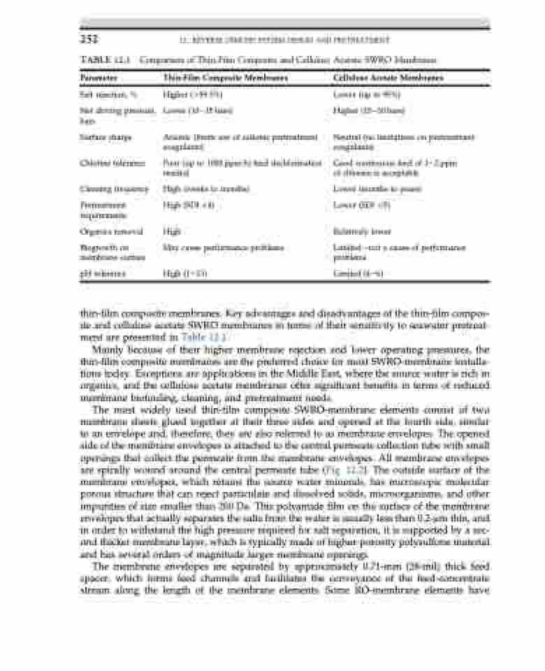
TABLE 12.1
Parameter
Salt rejection, %
Net driving pressure, bars
Surface charge Chlorine tolerance
Cleaning frequency
Pretreatment requirements
Organics removal
Biogrowth on membrane surface
pH tolerance
12. REVERSE OSMOSIS SYSTEM DESIGN AND PRETREATMENT
Comparison of Thin-Film Composite and Cellulose Acetate SWRO Membranes
Thin-Film Composite Membranes
Higher (>99.5%) Lower (10e15 bars)
Anionic (limits use of cationic pretreatment coagulants)
Poor (up to 1000 ppm-h) feed dechlorination needed
High (weeks to months) High (SDI <4)
High
May cause performance problems
High (1e13)
Cellulose Acetate Membranes
Lower (up to 95%) Higher (15e30 bars)
Neutral (no limitations on pretreatment coagulants)
Good continuous feed of 1e2 ppm of chlorine is acceptable
Lower (months to years) Lower (SDI <5)
Relatively lower
Limiteddnot a cause of performance problems
Limited (4e6)
thin-film composite membranes. Key advantages and disadvantages of the thin-film compos- ite and cellulose acetate SWRO membranes in terms of their sensitivity to seawater pretreat- ment are presented in Table 12.1.
Mainly because of their higher membrane rejection and lower operating pressures, the thin-film composite membranes are the preferred choice for most SWRO-membrane installa- tions today. Exceptions are applications in the Middle East, where the source water is rich in organics, and the cellulose acetate membranes offer significant benefits in terms of reduced membrane biofouling, cleaning, and pretreatment needs.
The most widely used thin-film composite SWRO-membrane elements consist of two membrane sheets glued together at their three sides and opened at the fourth side, similar to an envelope and, therefore, they are also referred to as membrane envelopes. The opened side of the membrane envelopes is attached to the central permeate collection tube with small openings that collect the permeate from the membrane envelopes. All membrane envelopes are spirally wound around the central permeate tube (Fig. 12.2). The outside surface of the membrane envelopes, which retains the source water minerals, has microscopic molecular porous structure that can reject particulate and dissolved solids, microorganisms, and other impurities of size smaller than 200 Da. This polyamide film on the surface of the membrane envelopes that actually separates the salts from the water is usually less than 0.2-mm thin, and in order to withstand the high pressure required for salt separation, it is supported by a sec- ond thicker membrane layer, which is typically made of higher-porosity polysulfone material and has several orders of magnitude larger membrane openings.
The membrane envelopes are separated by approximately 0.71-mm (28-mil) thick feed spacer, which forms feed channels and facilitates the conveyance of the feed-concentrate stream along the length of the membrane elements. Some RO-membrane elements have
