
Page 279 - ro membanes
P. 279
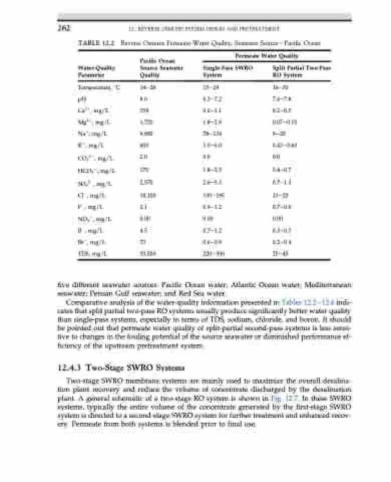
  262
12. REVERSE OSMOSIS SYSTEM DESIGN AND PRETREATMENT
TABLE 12.2
Water-Quality Parameter
Temperature, C pH
Ca2þ, mg/L Mg2þ, mg/L Naþ, mg/L
Kþ, mg/L CO32, mg/L HCO3, mg/L SO42, mg/L Cl, mg/L
F, mg/L NO3, mg/L B, mg/L
Br, mg/L TDS, mg/L
Reverse Osmosis Permeate-Water Quality, Seawater SourcedPacific Ocean
 Pacific Ocean Source Seawater Quality
14e28 8.0 358 1,720 9,900 600 2.0
170 2,570
18,100 2.1 0.00 4.5
73 33,500
Permeate Water Quality
 Single-Pass SWRO System
15e29 6.3e7.2 0.6e1.1 1.8e2.8 78e134 3.0e6.0 0.0
1.8e2.5 2.6e5.3
130e195 0.9e1.2 0.00 0.7e1.2 0.6e0.9 220e350
Split Partial Two-Pass RO System
16e30 7.6e7.8 0.2e0.5 0.07e0.10 9e20 0.43e0.60 0.0
0.4e0.7 0.7e1.3
13e20 0.7e0.9 0.00 0.3e0.5 0.2e0.4 25e45
   five different seawater sources: Pacific Ocean water; Atlantic Ocean water; Mediterranean seawater; Persian Gulf seawater; and Red Sea water.
Comparative analysis of the water-quality information presented in Tables 12.2e12.6 indi- cates that split partial two-pass RO systems usually produce significantly better water quality than single-pass systems, especially in terms of TDS, sodium, chloride, and boron. It should be pointed out that permeate water quality of split-partial second-pass systems is less sensi- tive to changes in the fouling potential of the source seawater or diminished performance ef- ficiency of the upstream pretreatment system.
12.4.3 Two-Stage SWRO Systems
Two-stage SWRO membrane systems are mainly used to maximize the overall desalina- tion plant recovery and reduce the volume of concentrate discharged by the desalination plant. A general schematic of a two-stage RO system is shown in Fig. 12.7. In these SWRO systems, typically the entire volume of the concentrate generated by the first-stage SWRO system is directed to a second-stage SWRO system for further treatment and enhanced recov- ery. Permeate from both systems is blended prior to final use.
